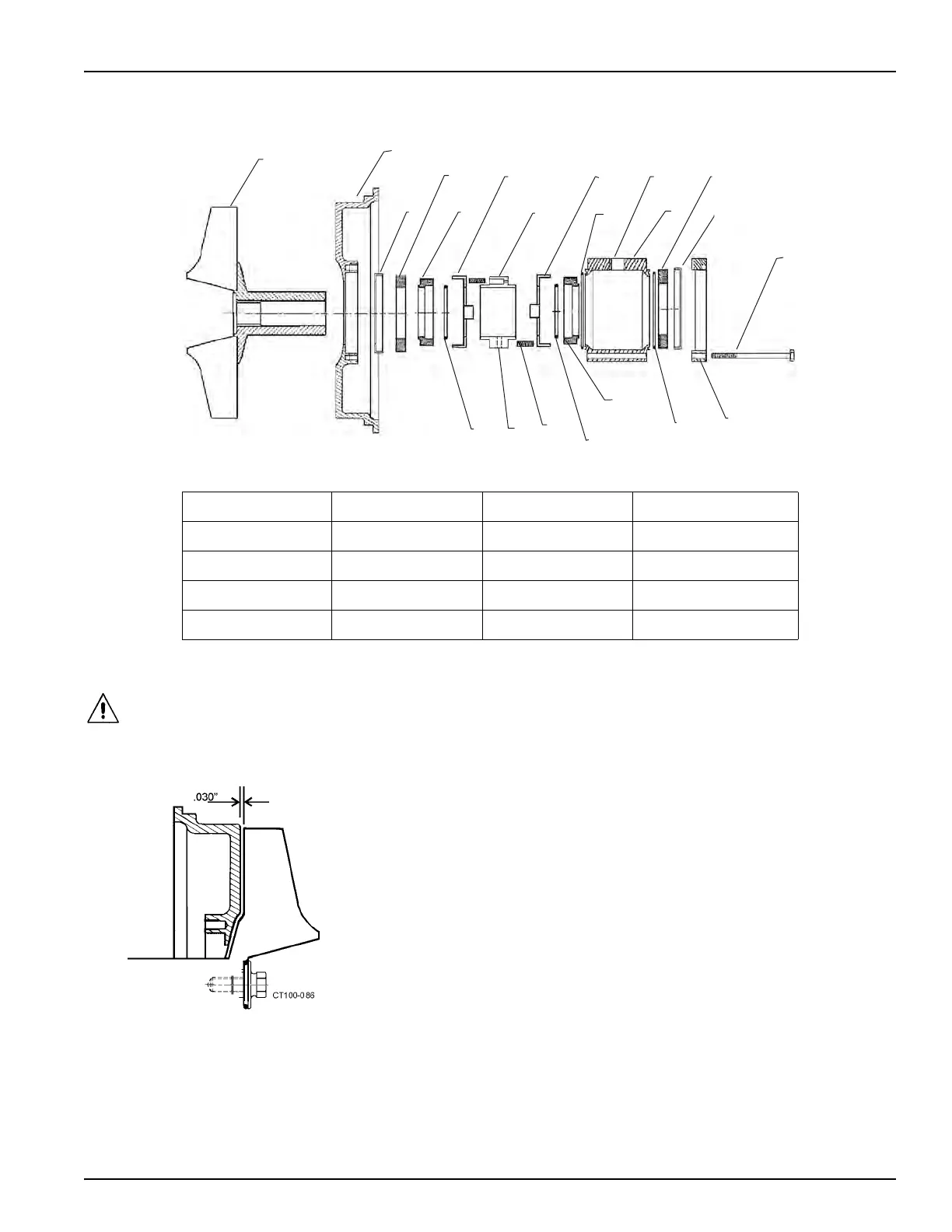
Figure 40 - Type 4 Seal Components
A. Impeller F. O-ring L. Rotary Seal S. Stationary Seal
B. Backplate G. Washer M. O-ring T. L-gasket
C. L-gasket H. Spring Retainer N. NPT Port U. Seat Retainer
D. Stationary Seal J. Spring P. Flush Housing V. Hex Head Screw (4)
E. Rotary Seal K. Washer R. O-ring W. Set Screw
Waukesha Cherry-Burrell Maintenance
10/2010 95-03009 Page 39
Assembly of Type 4 Seal
CAUTION: Handle the impeller/
backplate assembly with care to
prevent da
mage to the seal com-
ponents.
1. Clean all parts and lubricate all elastomer (rubber-like) parts.
2. Install the L-gasket in the backplate (Figure 40, items B and C).
3. Install the L-gasket in the seat retainer (Figure 40, item T).
4. Install the stationary seals (Figure 40, item S) in the L-gaskets.
5. Place the backplate and rotary seal onto the impeller shaft.
6. Temporarily put 0.03" shims between the impeller vane and back
plate
to a preset clearance. Be sure to remove the shims before
final assembly (Figure 41).
7. Place the o-ring (Figure 40, item F) on the shaft and use the spring
retainer to push the
o-ring into the rotary seal (Figure 42).
8. Place the washer (Figure 40, item G) over the rotary seal with tabs in
the outside diameter notches.
9. Place three springs (Figure 40, item J) in one side of the spring
retainer (item H). Hold them in place with silicone seal
er, and slide
the spring retainer (with the springs down) onto the impeller shaft the
against the washer.
Figure 41 - Shim Placement