Maintenance Waukesha Cherry-Burrell
Page 40 95-03009 10/2010
10. Place the remaining three (3) springs in the spring retainer.
11. Slide the washer and o-ring (Figure 40, items K and F) onto the shaft
against the spring retainer.
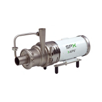
12. Use the spring retainer to press the o-ring into the rotary seal.
13. Remove the 1/4 NPT plug from the center port on the flush housing
(Figure 40, item N).
14. Install an o-ring (Figure 40, items M and R) in both ends of the hous-
ing.
15. Install the L-gasket in the seat retainer (Figure 40, items T and U).
16. Install the stationary seal (Figure 40, item S) in the L-gasket.
17. Install the housing over the seal assembly.
18. With flush ports facing away from the backplate, place the seat
re
ta
iner (Figure 40, item U) on the housing.
19. Tighten the seat retainer in place with four (4) hex screws (Figure 40,
item V).
NOTE: Be sure to tighten the screws evenly until full metal-to-metal con-
tact
is made on the backplate and seat retainer.
20. Install the original shims on the motor adapter shaft.
21. Install the backplate with the seal assembly and impeller on the motor
shaft.
22
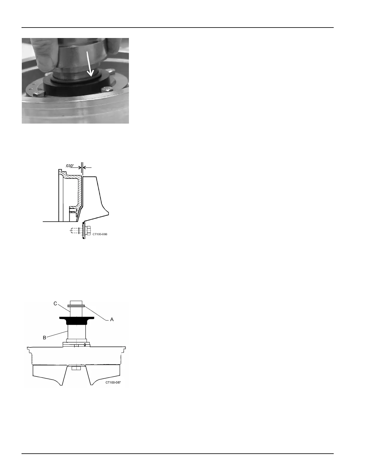
. Check the impeller/backplate clearance with the backplate held firmly
in po
sition against the motor adapter. Check the space between the
back of the impeller and the backplate with a feeler gauge (0.030"
nominal) while holding the backplate tight against the bearing housing
flange. Any axial movement of the shaft should not be added to the
0.030" nominal clearance (Figure 43). If needed, change this clear-
ance by adding or remov
i
ng shims. Shims (Figure 44, item A) are
added on the drive shaft (Figure 44, item C) behind the impeller shaft
(Figure 44, item B).
23. Confirm the operating clearances by clamping the casing to the bear-
ing housing flange and rotating the shaft/impeller manually to be sure
the
impeller does not touch the casing or backplate.
24. Tighten the set screws in the spring retainer through the 1/4" NPT
cent
er port in the flush housing (Figure 40, item N).
25. Insert the plug in the port and tighten it.
26. Remove the backplate/impeller assembly and apply anti-seize or
equa
l compound to the motor shaft and install the key.
27. Install the backplate/impeller assembly and lock it in place using the
o-r
ing and impeller retainer bolt.
Figure 42 - Installing O-ring Using Spring
Retainer
Figure 43 - Clearance Between Impeller
and Backplate
Figure 44 - Locations of Shims