Installation Waukesha Cherry-Burrell
Page 26 95-03009 10/2010
Installations That May Cause Operation Problems
• This pump is not self priming. If the pump is installed above the
supply liquid level, install a foot valve or other system check valve to
keep the system flooded for priming (Figure 17, item A)
• A throttling valve may be required to control the pump flow rate to
prevent
motor overload. Always install the throttling valve (Figure 17,
item B) in the discharge piping, at least 10 pipe diameters from the
pump outlet.
• Never install a throttling valve in th
e supply piping (Figure 17, item C).
• Any system throttling valves or similar devices to control the flow rat
e
must be installed in the discharge line. Do not install any system
throttling valves or similar devices to control the flow rate in the
supply line. Restriction in the supply line may cause cavitation and
pump damage.
• “Water hammer” in the system can damage the pump and other
system
comp
on
ents. Water hammer often occurs when valves in the
system are suddenly closed, causing lines to move violently and with
a loud noise. When this condition is present, find and eliminate the
source of the water hammer. One way to eliminate water hammer is
to slow down the actuation speed of the valve.
• Do not expose the pump to freezing temperatures with liquid in the
casing. Frozen liquid in
the cas
ing will damage the pump. Drain the
casing before exposing it to freezing temperatures.
Electrical Connections WARNING: To avoid electrocution, ALL electrical installation
should be done by a registered Electrician, following Industry
Safety Standards. All power must be OFF and LOCKED OUT
during installation.
• Read the motor manufacturer's instructions before starting the
installation. Follow the manufacturer's lubrication schedules.
• Check the motor nameplate to be sure the motor is compatible with
the electrical su
pply and all wiring, switches, and starters. Make sure
all overload protections are correctly sized (Figure 18).
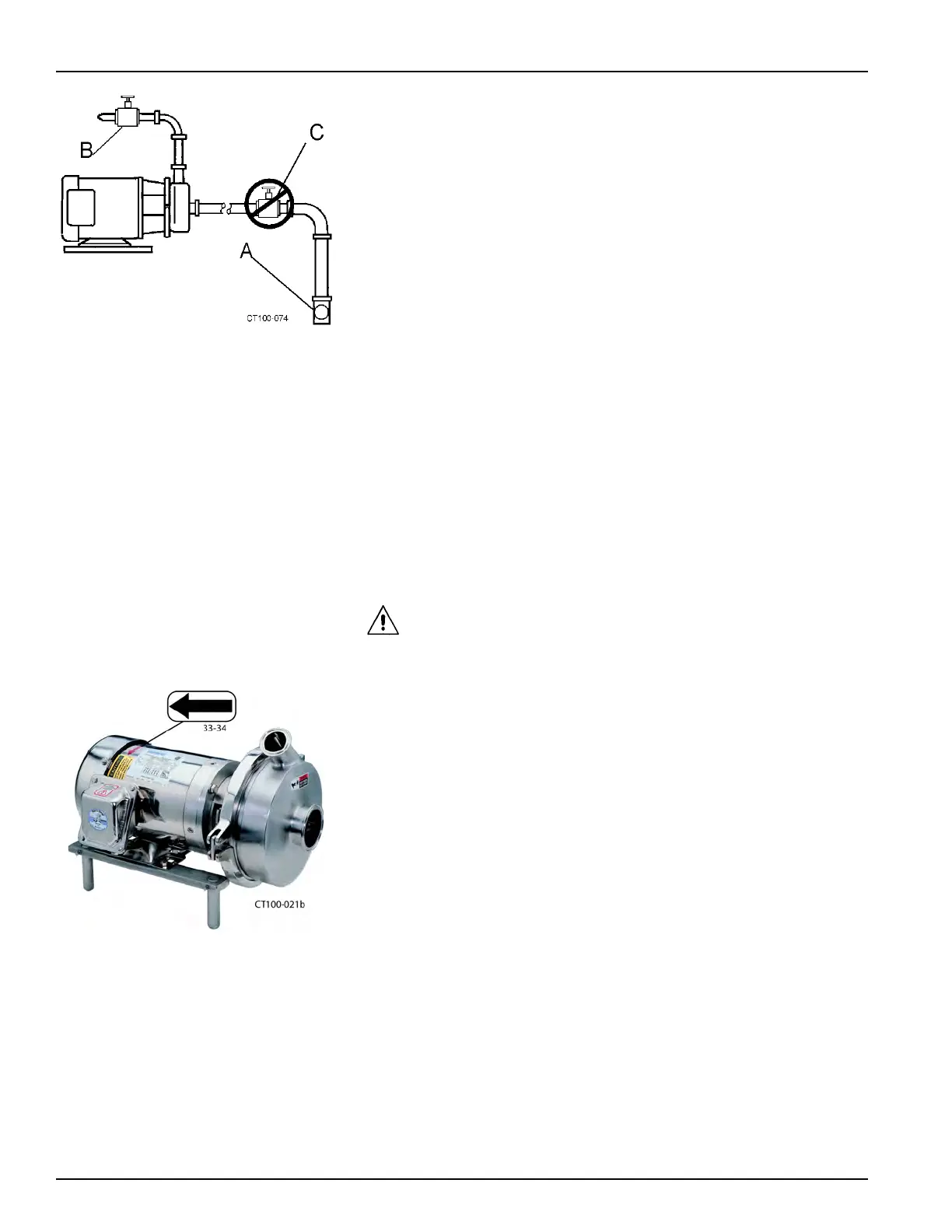
• Check the pump rotation following the electrical installation. The
correc
t rotation is counterclockwise when facing the pump inlet
connection (Figure 14 and Figure 18).
Figure 17 - Valve Piping Installation
Figure 18 - Direction of Motor Rotation