Electrical characteristics L6470
14/64 Doc ID 16737 Rev 2
t
hCK
t
lCK
SPI clock high and low time
(5)
TBD ns
t
setCS
Chip select setup time
(5)
TBD ns
t
holCS
Chip select hold time
(5)
TBD ns
t
disCS
Deselect time
(5)
TBD ns
t
setSDI
Data input setup time
(5)
TBD ns
t
holSDI
Data input hold time
(5)
TBD ns
t
enSDO
Data output enable time
(5)
TBD ns
t
disSDO
Data output disable time
(5)
TBD ns
t
vSDO
Data output valid time
(5)
TBD ns
t
holSDO
Data output hold time
(5)
TBD ns
Switch input (SW)
R
PUSW
SW input pull-up resistance SW = GND 60 85 110 kΩ
PWM modulators
f
PWM
Programmable PWM frequency
(1)
f
osc
= 16MHz 2.8 62.5
kHz
f
osc
= 32MHz 5.6 125
N
PWM
PWM resolution 8 bit
Overcurrent protection
OCD_th
MAX
Maximum programmable overcurrent
detection threshold
OCD_TH = ‘1111’ 6 A
OCD_th
MIN
Minimum programmable overcurrent detection
threshold
OCD_TH = ‘0000’ 0.375 A
OCD_th
RES
Programmable overcurrent detection threshold
resolution
0.375 A
t
OCD,Flag
OCD to Flag signal delay time
dI
out
/dt = 350A/µs,
R
FLAG
= TBD
650 1000 ns
t
OCD,SD
OCD to shut-down delay time
dI
out
/dt = 350A/µs
POW_SR = '10'
600 µs
V
FLAG
,
V
BUSY
Open drain low level output voltage I
od
= 4mA 0.3 V
Standby
I
qSTBY
Quiescent motor supply current in standby
conditions
V
S
= 8V 26 34
µA
V
S
= 36V 30 36
t
STBY,min
Minimum standby time 10 μs
t
logicwu
Logic power-on and wake-up time 38 45 µs
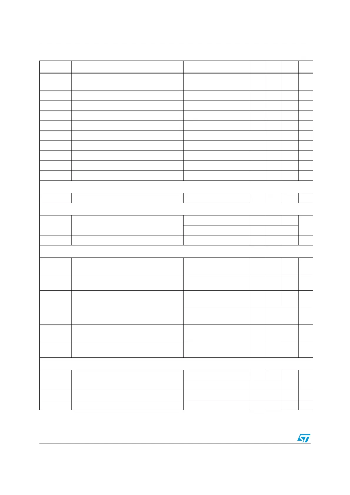
Table 4. Electrical characteristics (continued)
Symbol Parameter Test condition Min Typ Max Unit