L6470 Programming manual
Doc ID 16737 Rev 2 45/64
the synchronization signal is obtained starting from electrical position information (EL_POS
register) according to following
Ta ble 9 :
9.1.20 ALARM_EN
The ALARM_EN register allows selecting which alarm signals are used to generate the
FLAG output. If the respective bit of ALARM_EN register is set high, the alarm condition
forces the FLAG pin output down.
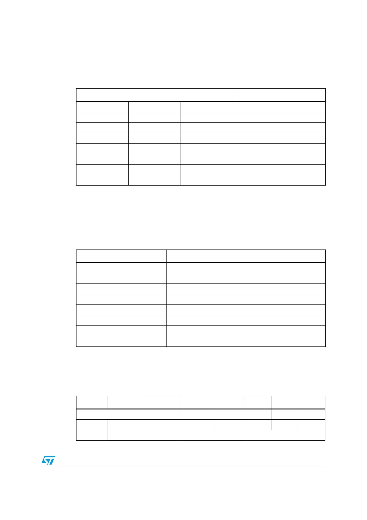
9.1.21 CONFIG
The CONFIG register has the following structure:
Table 19. SYNC signal source
SYNC_SEL[2..0] Source
0 0 0 EL_POS[7]
0 0 1 EL_POS[6]
0 1 0 EL_POS[5]
0 1 1 EL_POS[4]
1 0 0 EL_POS[3]
1 0 1 EL_POS[2]
1 1 0 EL_POS[1]
1 1 1 EL_POS[0]
Table 20. ALARM_EN register
ALARM_EN bit Alarm condition
0 (LSB) Overcurrent
1 Thermal shutdown
2 Thermal warning
3 Under-voltage
4 Stall detection (Bridge A)
5 Stall detection (Bridge B)
6 Switch turn-on event
7 (MSB) Wrong or not performable command
Table 21. CONFIG register
Bit 15 Bit 14 Bit 13 Bit 12 Bit 11 Bit 10 Bit 9 Bit 8
F_PWM_INT F_PWM_DEC POW_SR
Bit 7 Bit 6 Bit 5 Bit 4 Bit 3 Bit 2 Bit 1 Bit 0
OC_SD RESERVED EN_VSCOMP SW_MODE EXT_CLK OSC_SEL