L6470 Functional description
Doc ID 16737 Rev 2 25/64
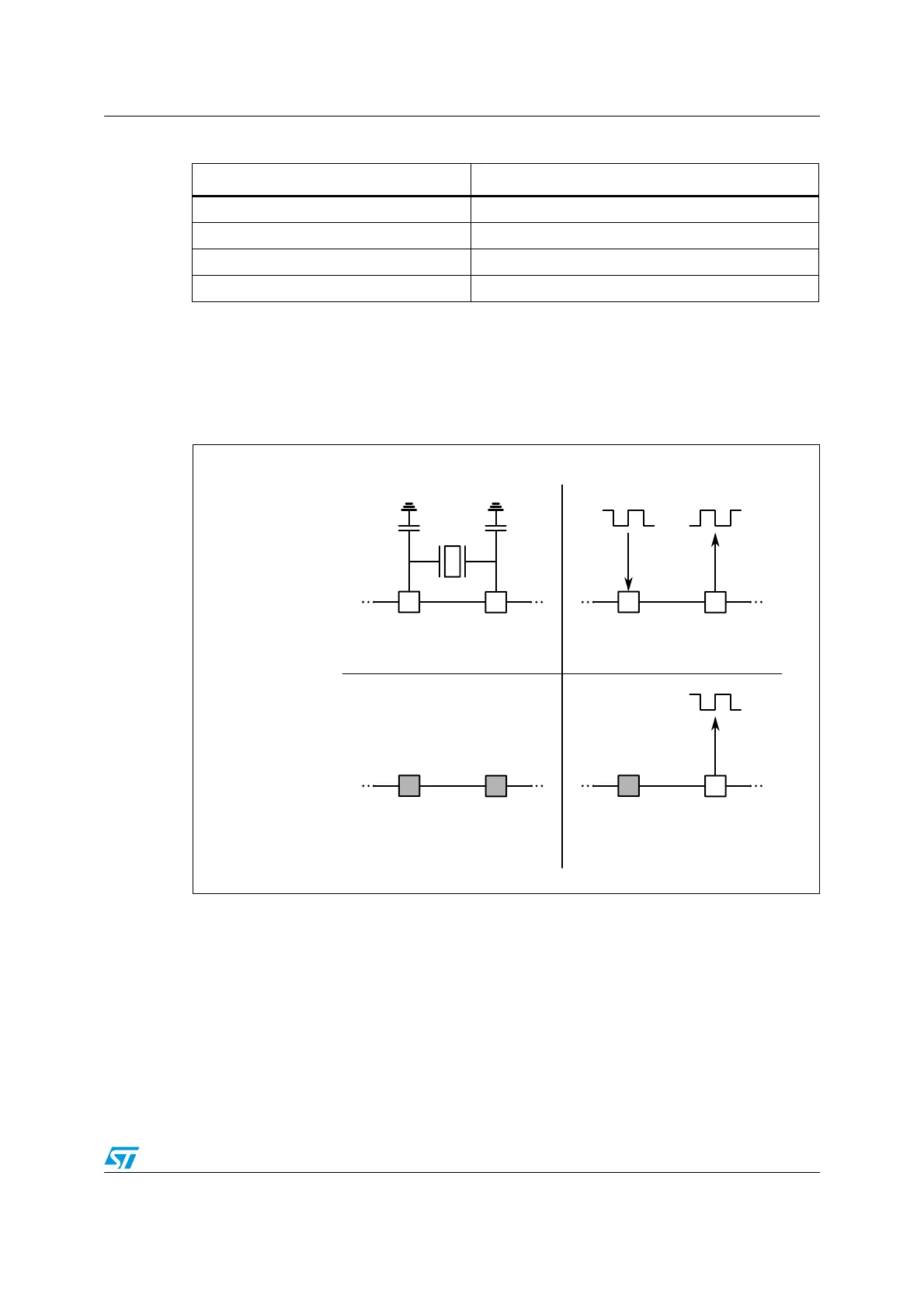
If a direct clock source is used, it must be connected to OSCIN pin and OSCOUT pin
supplies the inverted OSCIN signal (see Figure 10).
Figure 10. OSCIN and OSCOUT pins configurations
Note: When OSCIN is UNUSED, it should be connected to ground.
When OSCOUT is UNUSED it should be left floating.
6.9 Overcurrent detection
When the current in any of the power MOSFETs exceeds a programmed overcurrent
threshold, STATUS register OCD flag is forced low until the overcurrent event is expired and
a GetStatus command is sent to the IC (see paragraphs 9.1.22 and 9.1.17). Overcurrent
event expires when all the power MOSFET currents fall below the programmed overcurrent
threshold.
Table 7. CL values according to external oscillator frequency
Crystal/resonator freq.
(1)
1. First harmonic resonance frequency.
C
L
(2)
2. Lower ESR value allows driving greater load capacitors.
8MHz 25pF (ESR
max
= 80Ω)
16MHz 18pF (ESR
max
= 50Ω)
24MHz 15pF (ESR
max
= 40Ω)
32MHz 10pF (ESR
max
= 40Ω)
!-V
5.53%$
/3#). /3#/54 /3#). /3#/54
/3#). /3#/54
-(Z
-(Z
-(Z
%XTERNALOSCILLATOR
CONFIGURATION
%XTERNALCLOCKSOURCE
CONFIGURATION
)NTERNALOSCILLATOR
CONFIGURATION
WITHCL
OCKGENERATION
/3#). /3#/54
)NTERNALOSCILLATOR
CONFIGURATION
WITHOUTCLOCKSOURC
E
5.53%$ 5.53%$
/3#?3%,XX
/3#?3%,XX
# , # ,
%84?#,+ %84?#,+