L6470 Programming manual
Doc ID 16737 Rev 2 37/64
9.1.1 ABS_POS
The ABS_POS register contains the current motor absolute position in agreement to the
selected step mode; the stored value unit is equal to the selected step mode (full, half,
quarter, etc.). The value is in two's complement format and it ranges from -2
21
to +2
21
-1.
At power-on the register is initialized to “0” (HOME position).
Any attempt to write the register when the motor is running causes the command to be
ignored and the NOTPERF_CMD flag to rise (see paragraph
9.1.22).
9.1.2 EL_POS
The EL_POS register contains the current electrical position of the motor. The two MSbits
indicate the current step and the other bits indicate the current microstep (expressed in
step/128) within the step.
When the EL_POS register is written by the user the new electrical position is instantly
imposed. When the EL_POS register is written its value must be masked in order to match
with the step mode selected in STEP_MODE register in order to avoid a wrong microstep
value generation (see paragraph
9.1.19); otherwise the resulting microstep sequence will be
incorrect.
Any attempt to write the register when the motor is running causes the command to be
ignored and the NOTPERF_CMD flag to rise (see paragraph
9.1.22).
h18 CONFIG IC configuration 16 2E88
Internal oscillator,
2MHz OSCOUT clock,
supply voltage compensation
disabled,
overcurrent shutdown enabled,
slew-rate = 290 V/µs
PWM frequency = 15.6kHz.
R, WH
h19 STATUS Status 16 XXXX
(2)
High impedance state,
UVLO/Reset flag set.
R
h1A RESERVED Reserved address
h1B RESERVED Reserved address
1. R: Readable, WH: writable only when outputs are in high impedance, WS: writable only when motor is stopped, WR:
always writable.
2. According to startup conditions.
Table 8. Registers map (continued)
Address
[Hex]
Register name Register function
Len.
[bit]
Reset
Hex
Reset
Value
Remarks
(1)
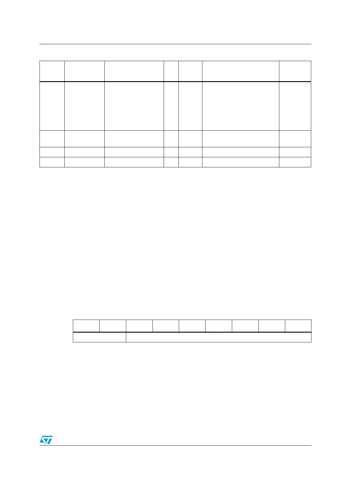
Table 9. EL_POS register
Bit 8 Bit 7 Bit 6 Bit 5 Bit 4 Bit 3 Bit 2 Bit 1 Bit 0
STEP MICROSTEP