Pin connection L6470
16/64 Doc ID 16737 Rev 2
4 Pin connection
4.1 Pin list
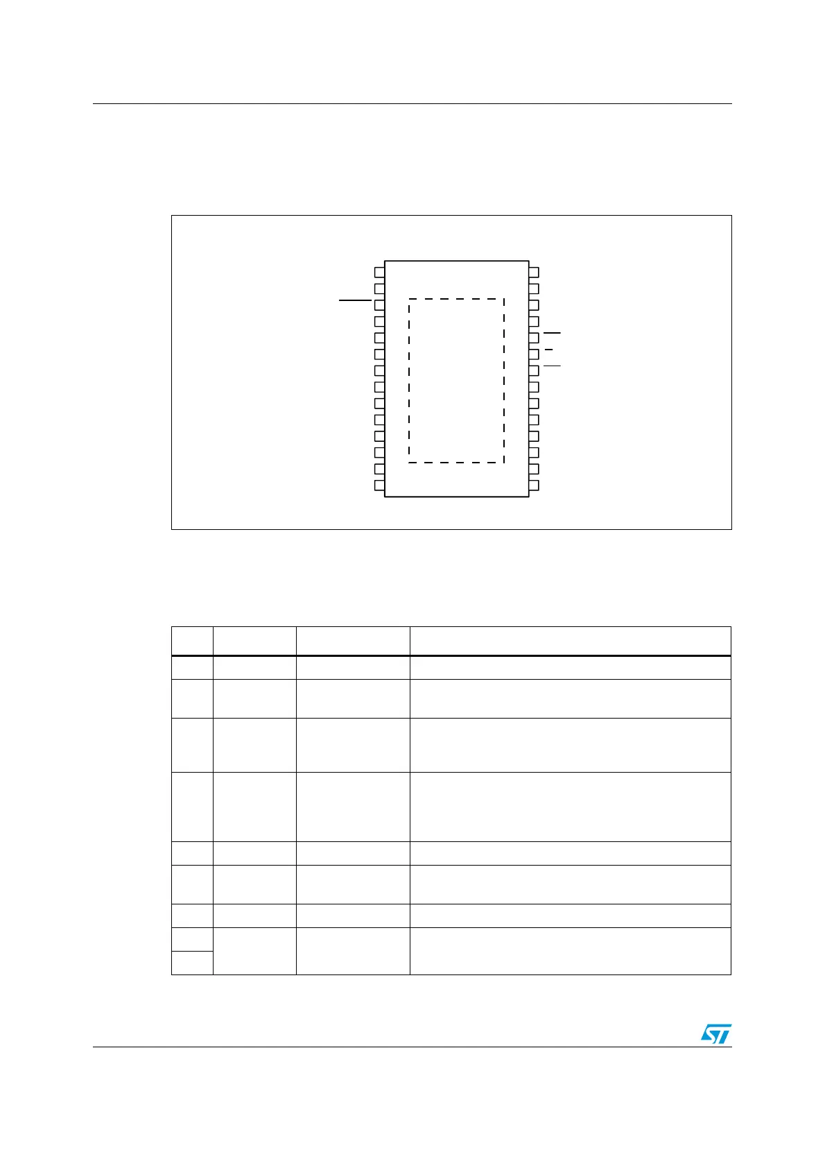
Figure 2. Pin connection (top view)
/54! /54!
63!
34"9<2%3
37
!$#).
62%'
/3#).
/3
#/54
!'.$
#0
6"/
/4
0'.$
63"
/54" /54"
63"
6$$
3$/
#+
3$)
$'.$
"539<39.#
#3
&,!'
34#+
0'.$
63!
%0!$
!-V
Table 5. Pin description
N. Name Type Function
17 VDD Power Logic outputs supply voltage (pull-up reference)
6VREG Power
Internal 3 V voltage regulator output and 3.3 V external
logic supply
7 OSCIN Analog input
Oscillator pin 1. To connect an external oscillator or clock
source. If this pin is UNUSED, it should be connected to
ground.
8 OSCOUT Analog output
Oscillator pin 2. To connect an external oscillator. When
the internal oscillator is used this pin can supply a
2/4/8/16 MHz. If this pin is UNUSED, it should be left
floating.
10 CP Output Charge pump oscillator output
11 VBOOT Supply voltage
Bootstrap voltage needed for driving the high side power
DMOS of both bridges (A and B)
5 ADCIN Analog input Internal analog to digital converter input
2
VSA Power supply
Full bridge A power supply pin. must be connected to
V
SB
26