UM2435 Rev 2 25/48
UM2435 Hardware layout and configuration
47
7.4 Embedded ST-LINK/V2-1
The ST-LINK/V2-1 programming and debugging tool is integrated on the Nucleo board.
The new features supported on ST-LINK/V2-1 are:
• USB software re-enumeration
• Virtual Com port interface on USB
• Mass storage interface on USB
• USB power management request for more than 100 mA on USB
The following features are no longer supported on ST-LINK/V2-1:
• SWIM interface
• Application voltage lower than 3 V (a level shifter is needed to support it)
For all general information concerning debugging and programming features common
between V2 and V2-1 versions, refer to UM1075 “ST-LINK/V2 in-circuit
debugger/programmer for STM8 and STM32”, available on www.st.com.
Nucleo-68 optional configuration for ST-LINK:
• The Nucleo-68 board is divided in two parts: ST-Link part and target MCU part.
The PCB area dedicated to the first one can be cut to reduce board size. In this case
the second part can only be powered by VIN, E5V and 3.3V on ST Morpho connectors,
or VIN and 3.3V on Arduino™ connectors.
• It is still possible to use the ST-Link part to program the main MCU using wires between
SWD connector and SWD signals available on ST Morpho connectors.
7.4.1 Drivers
Before connecting the Nucleo board to a Windows
®
PC (XP, 7, 8 or 10) via USB, a driver for
the ST-LINK/V2-1 (available on www.st.com) must be installed.
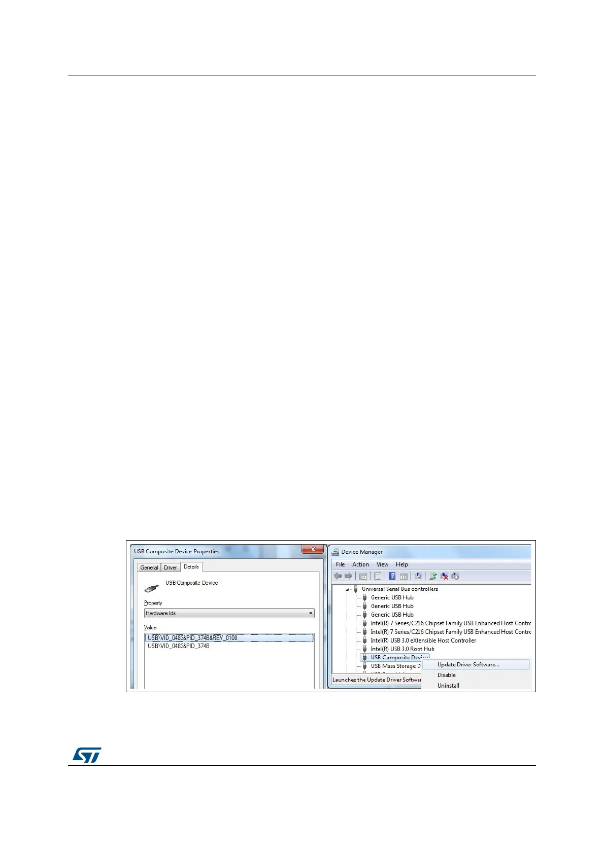
If the Nucleo board is connected to the PC before the driver is installed, some interfaces
may be declared as “unknown” in the PC device manager. In this case the user must install
the driver files, and update the driver of the connected device from the device manager.
Note: Use preferably the “USB Composite Device” handle for a full recovery.
Figure 16. USB composite device
 Loading...