Hardware layout and configuration UM2435
30/48 UM2435 Rev 2
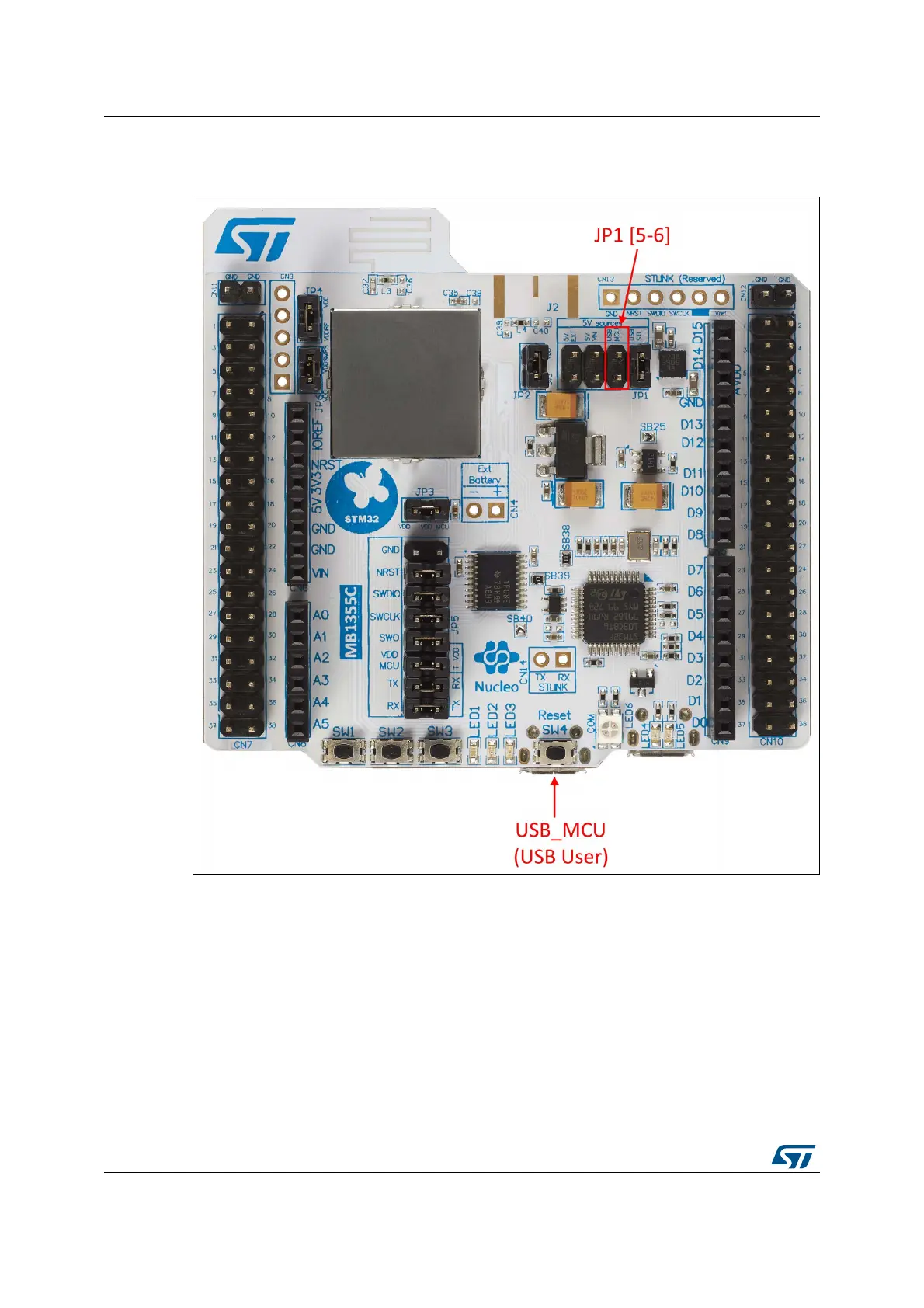
In the 5V_USB_MCU configuration JP1 [5-6] must be connected as shown in Figure 20.
Figure 20. JP1[5-6]: 5V_USB_MCU power source
Caution: A solder bridge (SB25) can be used (not an ST recommended setting) to bypass the USB
PWR protection STMPS2141STR. SB25 can be set only if the board is powered by USB PC
and maximum current consumption on 5V_STLINK doesn’t exceed 100 mA (including an
extension board or Arduino™ Shield). In such condition USB enumeration will always
succeed since no more than 100 mA is requested to the PC. Possible configurations of
SB25 are summarized in Table 6.
 Loading...