UM2435 Rev 2 31/48
UM2435 Hardware layout and configuration
47
Caution: If the maximum current consumption by the Nucleo and its extension boards exceeds
500 mA it is recommended to power the board using an external power supply connected to
E5V or VIN.
7.5.2 External power supply output
5V: when the Nucleo board is powered by USB, VIN or 5V_EXT, the 5V (CN6 pin 5 or CN7
pin 18) can be used as output power supply for an Arduino™ shield or an extension board.
In this case, the maximum current specified in
Table 5 needs to be respected.
3V3 on CN6 pin 4 or CN7 pin 16 can be used as power supply output. The current is limited
by the maximum capability of the regulator U3 (LD39050PUR33 from STMicroelectronics),
that is 500 mA for the Nucleo board and its shield.
7.5.3 Internal power supply
The device allows the application to meet the tight peak current requirements imposed by
the use of standard coin cell batteries. When the high efficiency embedded SMPS
step-down converter is used, the RF front end consumption (I
tmax
) is reduced.
It is possible to be also in LDO mode by changing the firmware, SB31 needs to be closed.
7.6 Programing/debugging when the power supply
is not from USB ST-LINK (5V_ST_link)
VIN or 5V_EXT can be used as external power supply if the current consumption of Nucleo
and extensions boards exceeds the allowed current on USB. In this condition it is still
possible to use the USB for communication for programming or debugging only.
In this case it is mandatory to power the board first using VIN or 5V_EXT, then connecting
the USB cable to the PC. The enumeration succeeds thanks to the external power source.
The following power sequence procedure must be respected:
1. Configure jumper JP1 to select between VIN or 5V_EXT, see Section 7.3.1
2. Be sure that SB37 is removed
3. Connect the external power source to VIN or E5V
4. Power ON the external power supply 7 V < VIN < 12 V to VIN, or 5 V for 5V_EXT
5. Check that the green LED is turned ON
6. Connect the PC to USB connector CN15
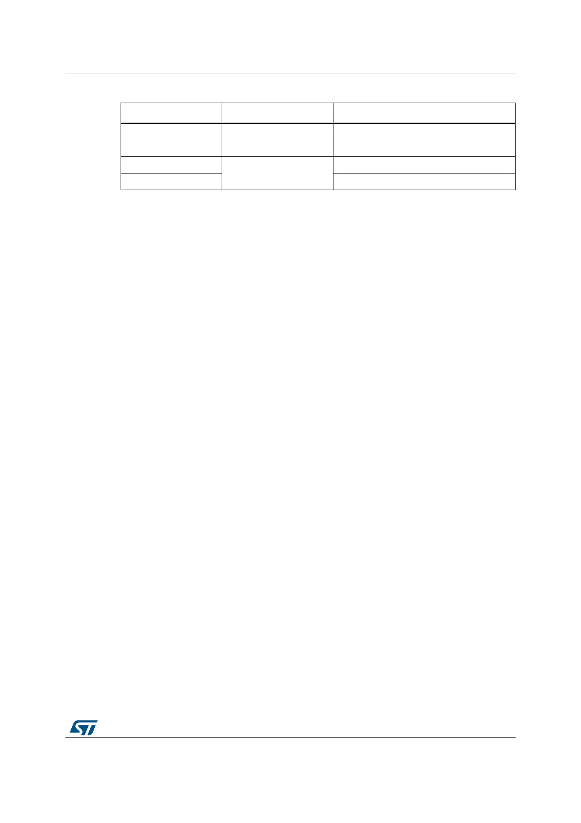
Table 6. SB25 bypass USB PWR protection
Default position Power sypply Allowed current
OFF (not soldered)
USB PWR through CN15
500 mA max (limited by STMPS2141STR)
ON (soldered) 500 mA max
OFF (not soldered)
VIN or E5V PWR
No limitation
ON (soldered) Forbidden configuration
(1)
1. SB25 must be removed when the board is powered by 5V_EXT (CN7 pin 6) or by VIN (CN6 pin 8).
 Loading...