Hardware layout and configuration UM2435
28/48 UM2435 Rev 2
and its shield can use up to 500 mA. If the host is unable to provide the requested current,
the enumeration fails. Therefore the power switch STMPS2141STR remains OFF and the
MCU is not powered. As a consequence LED5 remains turned OFF. In this case it is
mandatory to use an external power supply.
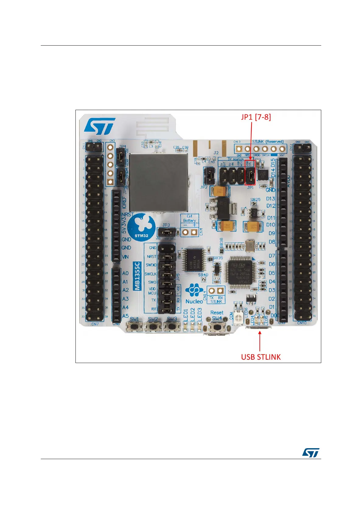
In this configuration JP1[7-8] must be connected as in Figure 18.
Figure 18. JP1[7-8]: 5V_STL power source
VIN is the 7 to 12 V DC power from ARDUINO™ CN8 pin 8 named VIN on Arduino™
connector silkscreen, or from Morpho connector CN7-24, or from external connector CN4.
In this case JP1 has to be on pin [3-4] to select VIN power source on silkscreen of JP1. The
DC power can come from the power supply through the Arduino™ UNO V3 battery shield
(compatible with Adafruit
®
PowerBoost 500 Shield).
 Loading...