For target applications having significant current consumption, it is recommended to use cables with adapted
conductor diameter to limit voltage drop through the cable due to wire resistance and current consumption of the
target application.
In addition, it is recommended to not use wires longer than ~30 cm and twist them (OUT and GND wires) to
reduce parasitic inductance.
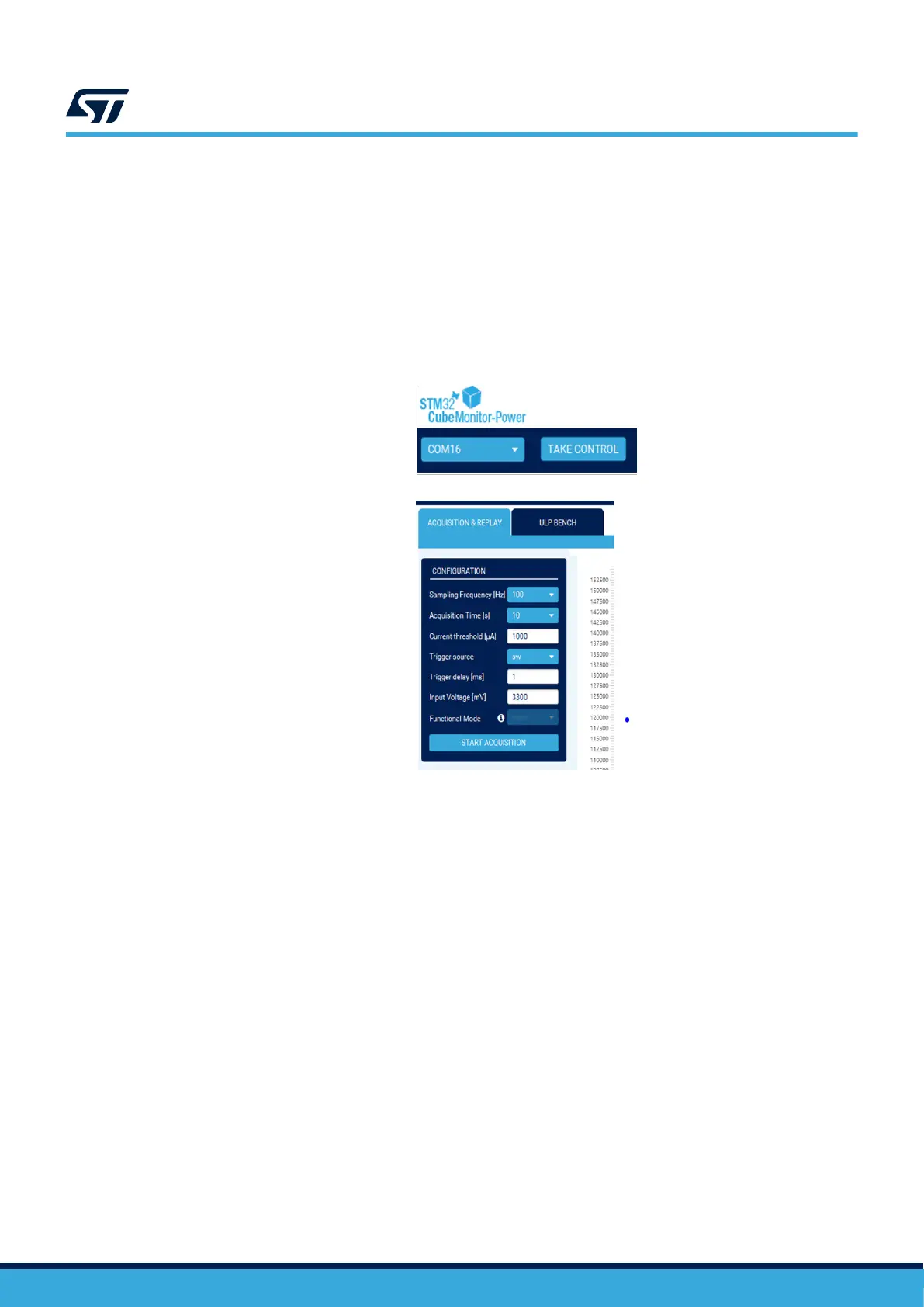
6.2 Software configuration
1. Launch the STM32CubeMonitor-Power application.
2.
Select the COM port of the device.
Figure 5. STM32CubeMonitor-Power setting
3. Click on the "TAKE CONTROL" button to handle the STLINK-V3PWR probe.
– ACQUISITION & REPLAY:
– Set "Sampling Frequency" to 20000 Hz [recommended value]
– Set "Acquisition Time" to 10 s
– Set "Current Threshold" to 1000 µA
– Set "Trigger Source" to "sw" (software)
– Set "Trigger Delay" to 1ms
– Set the desired "Input Voltage" of the target application inside the range 1600 mV/3600 mV
4. Click on the "START ACQUISITION" button
5. The STLINK-V3PWR's SMU turns on and current measurement acquisition starts:
– OUT and AUX LEDs turn on green (output voltage turned on)
– Current measurement is displayed in real time in the STM32CubeMonitor-Power main window.
Note: Refer to the user manual STM32CubeMonitor-Power software tool for power and ultra-low-power
measurements (UM2202).
UM3097
Software configuration
UM3097 - Rev 1
page 10/30