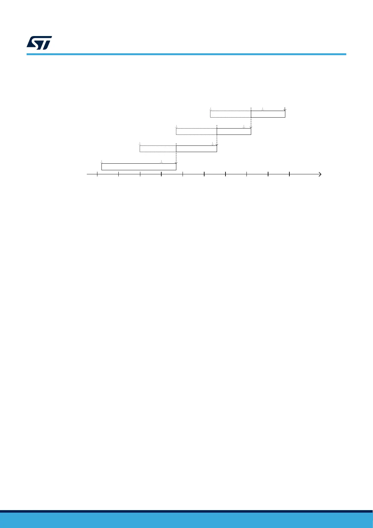
The four measurement paths have a fixed current range (refer to Figure 9). Range selections are fully automated
at run time by post‑processing algorithms allowing a continuous current acquisition from a few nA to 500 mA.
Figure 9. SMU current measurement ranges
DT59123V1
10
-9
1nA
Iout (A)
(load
)
10
-8
10
-7
10
-6
1 µA
10
-5
10
-4
10
-3
1 mA
10
-2
10
-1
1
1
A
res: 1.5 nA
5 µA
RANGE1
380 µA
RANGE2
RANGE3
15 mA
500 mA
RANGE4
res: 5 nA
res: 60 nA res: 1 µA
res: 5 µA
res: 15 µA
res: 150 µA
res: 250 µA
Impact of noise on sampling rate selection
The sampling rate selection has significant impacts on measurements.
Using the maximum sampling rate allows the user to catch fast current transient activities but it intrinsically
increases the noise level making small current variations hidden in the noise level.
Reciprocally
, using the minimum sampling rate allows the user to measure small current variations and average
the noise but it smooths fast current transient activities.
Note: Sampling rate selection does not impact the current measurement DC accuracy.
7.2.3 Self‑calibration management
STLINK-V3PWR has built‑in self‑calibration circuitry to compensate for the current measurements of
fset due to
temperature variation.
A self-calibration is automatically performed during current measurements acquisition every +/- 5°C temperature
change inside STLINK-V3PWR.
During the self-calibration sequence, STLINK-V3PWR keeps the SMU output voltage (OUT) enabled but STLINK-
V3PWR stops sending measurement data to the host PC. Once the self‑calibration sequence ends, STLINK-
V3PWR restarts sending measurement data to the host PC.
A self‑calibration sequence duration is approximately 15 ms and does not require user intervention.
Each time a self-calibration occurs:
• A popup is displayed on the STM32CubeMonitor-Power windows to inform the user that acquisition data is
stopped for self-calibration sequence duration.
• The OUT LED turns in orange color (refer to Table 8. OUT LED).
7.2.4 Overcurrent and short circuit management
The SMU output is protected against overcurrent higher than OCP
TH
(refer to T
able 12) and short circuits.
It can safely tolerate short overcurrent or peak current before triggering an OCP (overcurrent protection). This is
suitable to keep the target application operating without crashing during peak transient activities where current
consumption is higher than OCP
TH
.
When OCP
TH
< I
OUT
< OCP
MAX
, the output voltage decreases as the output current increases:
V
OUT
≈ V
OUTnom
– 0.3 x I
OUT
Short overcurrent
A short overcurrent is a current consumption within OCP
TH
< I
OUT
< OCP
MAX
having a duration less than
t
_short_ocp
(refer to Table 12).
Nevertheless, the SMU returns erroneous current measurement values to the host PC as the current consumption
is above the operating measurement area.
UM3097
SMU output (OUT)
UM3097 - Rev 1
page 13/30