5 Product information
5.1 Product content
The STLINK-V3PWR kit contains:
•
STLINK-V3PWR probe
• Four wires:
– Two wires male/male (red and black)
– Two wire male/female (red and black)
• Three debug cables allowing the connection from the STDC14 (DEBUG port) to:
– STDC14 connector (1.27 mm pitch) Samtec FFSD-07-D-05.90-01-N
– MIPI10/ARM10-compatible connector (1.27 mm pitch) Samtec FFSD-05/07-D-05.90-01-N
– MIPI20/ARM20-compatible connector (1.27 mm pitch) Samtec FFSD-10/07-D-05.90-01-N
Note: To support the JTAG interface, in 2.54 mm pitch, use a dedicated dongle MIPI/ARM20 to JTAG (2.54 mm) (for
example: dongle “JTAG 20 Pin 2.54 mm to 10 Pin 1.27 mm adapter”)
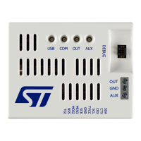
5.2 STLINK-V3PWR connectors and LEDs identification
This section aims to identify the location of the STLINK-V3PWR connectors and LEDs.
They are illustrated with the silkscreen on the casing serving as a functional reference for most connectors. A
connection overview is given here:
• USB-C:
USB Type-C
®
receptacle for host PC connection using a USB Type-C
®
to USB Type-C
®
cable for
the STLINK-V3PWR power supply and data transfer. Refer to Section 5.3 USB connection with a host PC.
• DEBUG: STDC14 2x7-pin male connector with 1.27 mm pitch for connection to an STM32 target
application for debugging operations. Three different flat cables are included in the packaging to connect
with standard connectors MIPI10/ARM 10, STDC14, and ARM 20. Refer to Section 9.3 DEBUG (STM32
JTAG/SWD and VCP).
• BRIDGE: 2x11-pin male connector with 2.54 mm pitch for connection to an STM32 target application for
data communication (typically STM32’s bootloader) with several common interfaces via a proprietary USB
interface. Refer to Section 9.4 BRIDGE (I
2
C, CAN, SPI, UART, and GPIO).
• POWER: 3-pin screw connector with a 5 mm pitch allows supplying the target application via two
independent programmable power source: OUT (refer to Section 7.2 SMU output (OUT)) and AUX (refer
to Section 7.3 Auxiliary power source output (AUX)).
• LEDs: 4x3-colors LED to indicate the state of the product. Refer to Section 7.6 LEDs management.
UM3097
Product information
UM3097 - Rev 1
page 6/30

 Loading...