The STLINK-V3PWR’s SMU operates as a 1‑quadrant voltage source and current meter
. The SMU operating
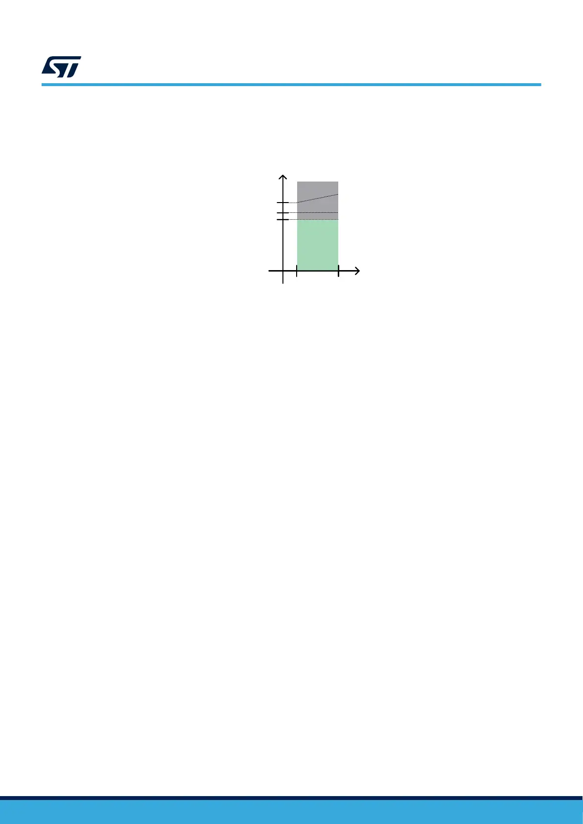
area is illustrated in Figure 8.
Figure 8. STLINK-V3PWR SMU operating area
DT59122V1
+1.6 V
+3.6 V
+500 mA
operating
measurement
area
0
I
OUT
V
OUT
OCP
TH
overcurrent
OCP
MAX
short-circuit
7.2.1 Voltage source
The SMU output voltage is programmable from +1.6 to +3.6 V by 100 mV step.
The SMU output voltage keeps stable and accurate over the operating measurement area (refer to Figure 8),
even with a large capacitive load (order of 100 µF) that usually causes SMU oscillating.
It has excellent load transient response, even for a transient starting from very low current to high current with
fast current rise time (refer to V
OUT_LO
in Table 12). This is especially suitable to supply an STM32 microcontroller
operating from STANDBY mode (very low current) to RUN mode (high current) without impacting its power supply
voltage.
The SMU can source a 500 mA continuous output current.
Above 500 mA and up to OCP
TH
(550 mA) output current, the SMU output starts entering self-protection mode.
Output voltage decreases slowly as output current increases.
It can safely tolerate overcurrent and short circuits (refer to Section 7.2.4 Overcurrent and short circuit
management).
Voltage source power ON/ power OFF management
• The voltage source is OFF after STLINK-V3PWR powers up (USB cable insertion).
• The default output voltage is 3.3 V. Any voltage change must be performed before turning on the voltage
source.
• By default, the voltage source is automatically turned ON when a current measurement acquisition is
started.
• By default, the voltage source stays ON after a current measurement acquisition ends or stops.
7.2.2 Current measurement
The STLINK-V3PWR SMU is composed of four analog current measurement paths having 50 kHz analog
bandwidth. Current sample acquisitions of the four measurement paths are performed by an STM32H745 using
two 12‑bit ADCs working in parallel, each at a 1.6 MHz sampling frequency
. The embedded post‑processing
algorithms aim to manage current range selection and to perform noise reduction. SMU provides a sampling rate
of up to 100 kSPS (kilosamples per second) and down to 1 SPS to the host PC via a USB interface.
UM3097
SMU output (OUT)
UM3097 - Rev 1
page 12/30