Table 4. USB host PC or hub port identification
USB host port Port identification STLINK-V3PWR compatibility
USB LED
color
Standard USB Type-A port (500 mA) OUT and AUX disabled orange
Charging USB Type-A port (1.5 A) OK green
USB Type-C
®(1)
port (1.5 or 3
A)
OK green
Charging USB Type-C
®
port (3 A)
OK green
1.
Some USB T
ype-C
®
ports without the “spark” logo might be advertised as 500 mA ports. In that case, STLINK-V3PWR
works with the OUT and AUX disabled and the USB LED lights in orange color.
Note: Connection to a USB charger is not a functional use case for STLINK-V3PWR. In that case, USB LED lights
in green color (valid power source) and COM LED blinks red color (waiting for USB enumeration). Refer to
Section 7.6 LEDs management.
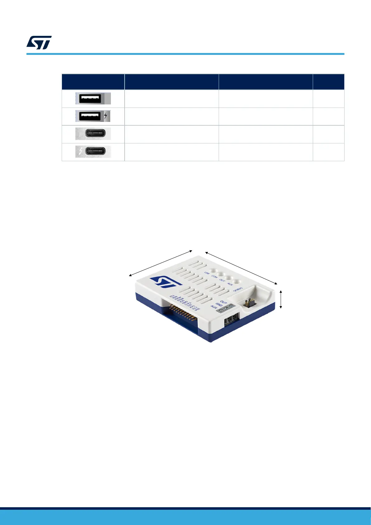
5.4 Mechanical information
Figure 3. Product dimensions
DT59117V1
90 mm
20 mm
70 mm
5.5 Thermal recommendation
STLINK-V3PWR is recommended to operate at the temperature range specified in T
able 11.
STLINK-V3PWR uses precision components that are affected by temperature changes. It is recommended to use
it at a place where the thermal gradient or airflow is minimum. A typical laboratory bench or table might be an
optimal location.
Accordingly, airflow cooling holes on the top and the bottom of STLINK-V3PWR must be kept free to ease air
cooling.
Hence it is recommended to start the measurement after waiting for a few minutes after the product is plugged
into the USB port and a connection is established. This ensures the entire product self‑heating to reach
thermal equilibrium and avoid triggering a self‑calibration sequence during measurement acquisition (refer to
Section 7.2.3 Self‑calibration management).
5.6 Known limitation
The STLINK-V3PWR internal acquisition circuitry is sensitive to vibration and shock. If vibration or shock occurs
during acquisition,
STLINK-V3PWR sends acquisition data containing erroneous peak current.
UM3097
Mechanical information
UM3097 - Rev 1
page 8/30