6 Quick start
This section describes how to start with STLINK-V3PWR to make power measurements:
1.
Check that the bundle is complete (STLINK-V3PWR with three flat cables and a bundle of four wire
jumpers).
2. Install or update the power measurement software (for example STM32CubeMonitor-Power).
3. Connect a USB Type-C
®
to USB Type-C
®
cable (recommended) or USB Type-A to USB Type-C
®
cable
between STLINK-V3PWR and the PC (refer to Section 5.3 USB connection with a host PC).
4. Check the LED status:
– The USB LED must turn green: STLINK-V3PWR is supplied by a valid power source from PC.
– The COM LED must turn red: STLINK-V3PWR debugger is ready.
5. Hardware configuration for power measurement: Connect the STLINK-V3PWR’s SMU (OUT and GND)
onto the power supply input of the target application using wire jumpers. Refer to Section 6.1 Typical
application.
6. Software configuration for power measurement: Refer to Section 6.2 Software configuration.
6.1 Typical application
6.1.1 Connection with a target application for power measurements
STLINK-V3PWR provides two voltage‑regulated power sources: OUT and AUX:
•
OUT is a programmable voltage‑regulated power source including current measurement: Refer to
Section 7.2 SMU output (OUT).
• AUX is a programmable voltage‑regulated power source only: Refer to Section 7.3 Auxiliary power source
output (AUX).
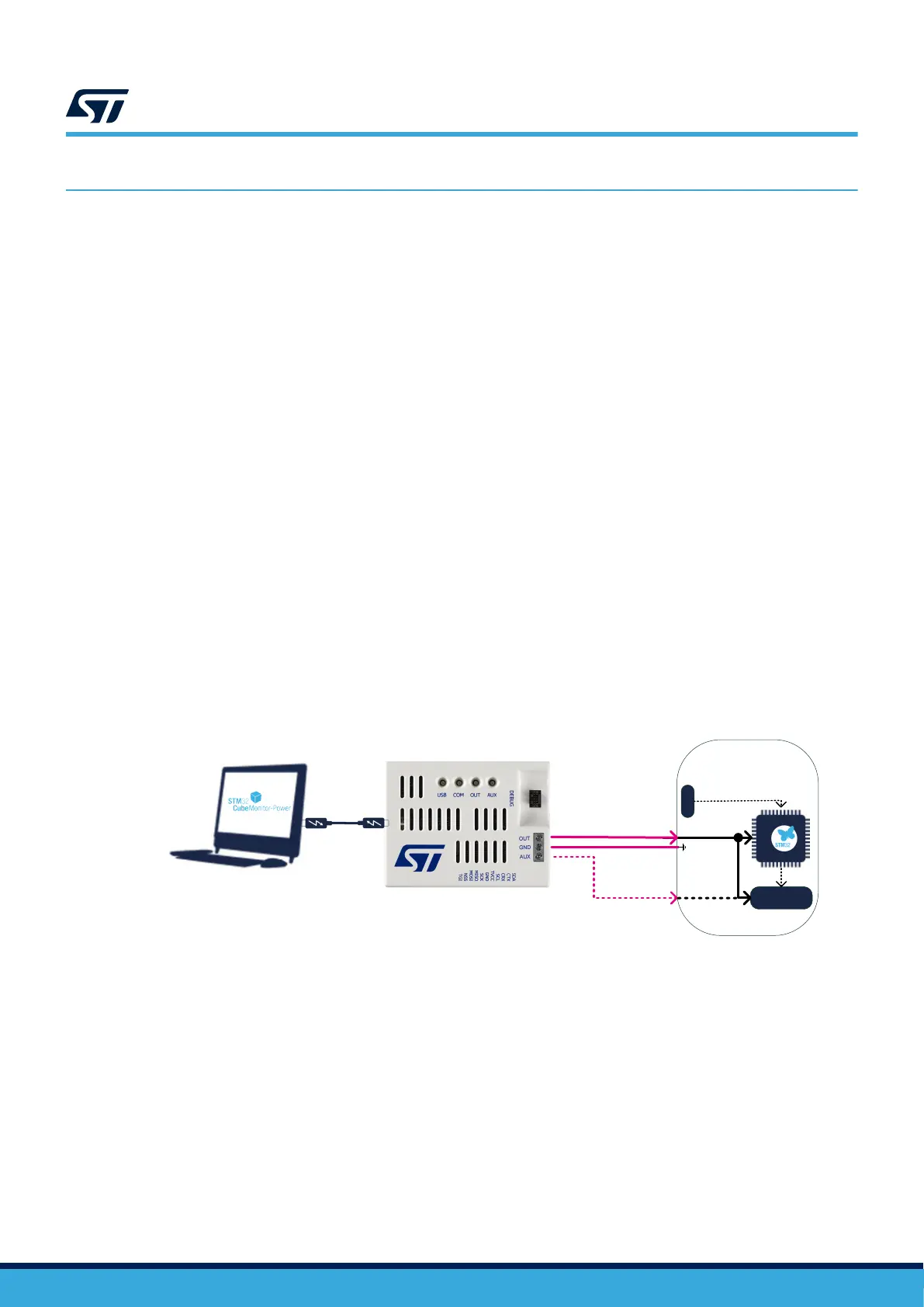
Figure 4 provides a basic connection example of STLINK-V3PWR with a target application.
Figure 4. STLINK-V3PWR connection
DT59118V1
VDD
Peripherals
Target
appl
ication
optional
+3V3
VDD
3V3_PERIPH
DEBUG
debug I/F
ctrl I/F
GND
• Connect OUT to the target application power supply input to be measured (for example pin +3V3 of an
STM32 Nucleo board) using a wire jumper provided in the kit.
•
Connect the GND to the target application ground (for example pin GND of an STM32 Nucleo board) using
a wire jumper provided in the kit.
• (Optional) Connect the AUX power source to the target application input power supply that does not require
to be measured.
6.1.2 Recommendations for power measurements
The use of wire jumpers provided in the kit must be limited to target applications not consuming more than
100 mA to avoid voltage drop through wire jumper cables.
UM3097
Quick start
UM3097 - Rev 1
page 9/30