EasyManuals Logo

ST STM32 User Manual

ST STM32
85 pages
To Next Page IconTo Next Page
To Previous Page IconTo Previous Page
Page #15 background imageLoading...
Page #15 background image
UM1974 Rev 9 15/85
UM1974 Hardware layout and configuration
84
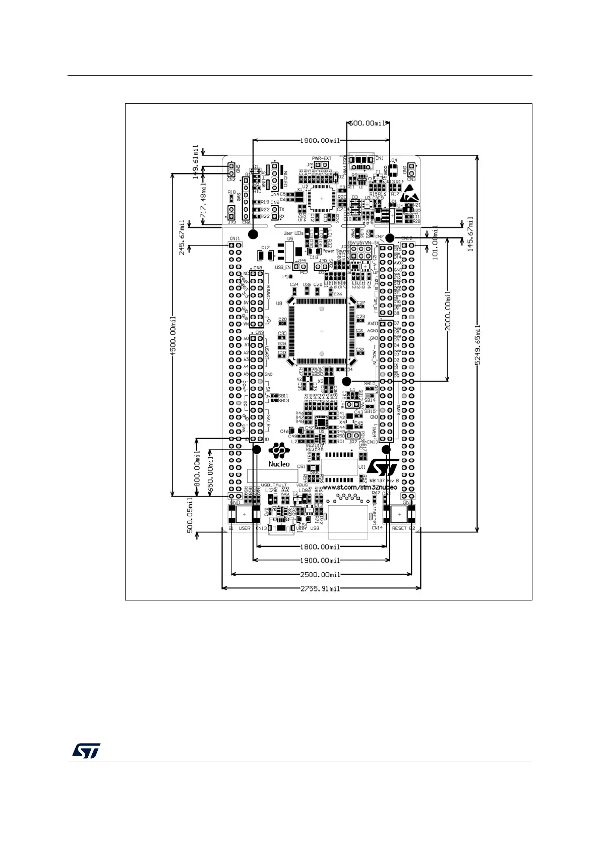
Figure 7. Nucleo-144 board mechanical drawing in mil
6.2 Cuttable PCB
The STM32 Nucleo-144 board is divided into two parts: ST-LINK and target STM32. The
ST-LINK part of the PCB can be cut out to reduce the board size. In this case the remaining
target STM32 part can only be powered by V
IN
, E5V and 3.3 V on ST morpho connector
CN11, or V
IN
and 3.3 V on ST Zio connector CN8. It is still possible to use the ST-LINK part
to program the STM32, using wires between CN6 and SWD available signals on the ST
morpho connector (SWCLK CN11 pin 15, SWDIO CN11 pin 13 and NRST CN11 pin 14).
MSv40075V1

Table of Contents

Other manuals for ST STM32

Questions and Answers:

Question and Answer IconNeed help?

Do you have a question about the ST STM32 and is the answer not in the manual?

ST STM32 Specifications

General IconGeneral
SeriesSTM32
CategoryMicrocontrollers
CoreARM Cortex-M0, Cortex-M0+, Cortex-M3, Cortex-M4, Cortex-M7, Cortex-M33
Clock SpeedUp to 480 MHz
GPIO PinsUp to 144
Communication InterfacesI2C, SPI, USART, USB, CAN, Ethernet
Package TypesLQFP, BGA, WLCSP
ADC Resolution12-bit, 16-bit (varies by series)
DAC Resolution12-bit (varies by series)
Operating Temperature-40°C to +85°C or +105°C

Related product manuals