EasyManuals Logo

ST STM32 User Manual

ST STM32
85 pages
To Next Page IconTo Next Page
To Previous Page IconTo Previous Page
Page #19 background imageLoading...
Page #19 background image
UM1974 Rev 9 19/85
UM1974 Hardware layout and configuration
84
6.3.4 Using ST-LINK/V2-1 to program and debug an external STM32
application
It is very easy to use the ST-LINK/V2-1 to program the STM32 on an external application.
Simply remove the two jumpers from CN4, as shown in Figure 10 and connect the
application to the CN6 debug connector according to Table 5.
Note: SB111 NRST (target STM32 RESET) must be OFF when CN6 pin 5 is used in an external
application.
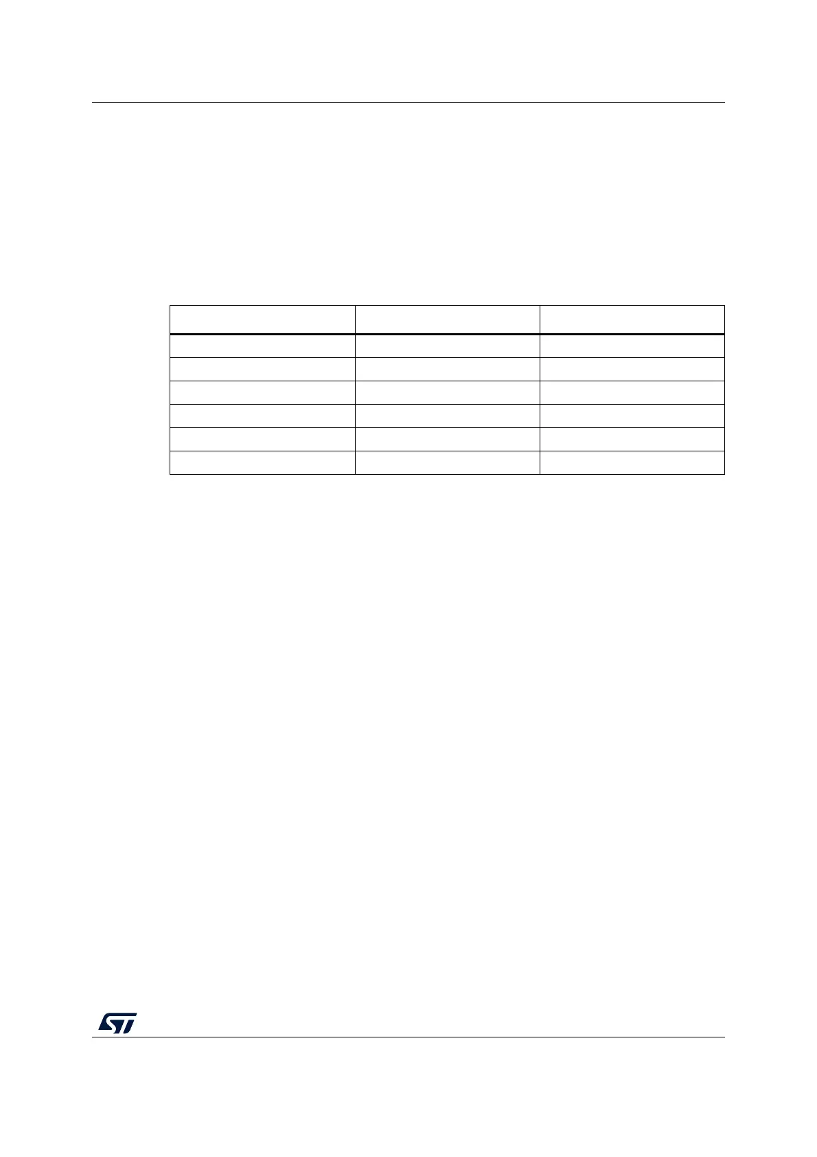
Table 5. Debug connector CN6 (SWD)
Pin CN6 Designation
1 VDD_TARGET VDD from application
2 SWCLK SWD clock
3 GND Ground
4 SWDIO SWD data input/output
5 NRST RESET of target STM32
6 SWO Reserved

Table of Contents

Other manuals for ST STM32

Questions and Answers:

Question and Answer IconNeed help?

Do you have a question about the ST STM32 and is the answer not in the manual?

ST STM32 Specifications

General IconGeneral
SeriesSTM32
CategoryMicrocontrollers
CoreARM Cortex-M0, Cortex-M0+, Cortex-M3, Cortex-M4, Cortex-M7, Cortex-M33
Clock SpeedUp to 480 MHz
GPIO PinsUp to 144
Communication InterfacesI2C, SPI, USART, USB, CAN, Ethernet
Package TypesLQFP, BGA, WLCSP
ADC Resolution12-bit, 16-bit (varies by series)
DAC Resolution12-bit (varies by series)
Operating Temperature-40°C to +85°C or +105°C

Related product manuals