Hardware layout and configuration UM1974
16/85 UM1974 Rev 9
6.3 Embedded ST-LINK/V2-1
The ST-LINK/V2-1 programming and debugging tool is integrated in the STM32 Nucleo-144
board.
The ST-LINK/V2-1 makes the STM32 Nucleo-144 board mbed enabled.
The embedded ST-LINK/V2-1 supports only SWD for STM32 devices. For information about
debugging and programming features refer to the ST-LINK/V2 in-circuit
debugger/programmer for STM8 and STM32 user manual (UM1075), which describes in
details all the ST-LINK/V2 features, and to the Overview of ST-LINK derivatives technical
note (TN1235).
The changes versus ST-LINK/V2 version are listed below.
Additional features supported on ST-LINK/V2-1:
• USB software re-enumeration
• Virtual com port interface on USB
• Mass storage interface on USB
• USB power management request for more than 100mA power on USB
Features not supported on ST-LINK/V2-1:
• SWIM interface
• Minimum supported application voltage limited to 3 V
There are two different ways to use the embedded ST-LINK/V2-1, depending on the jumper
state (see
Table 4):
• Program/debug the STM32 on board
• Program/debug the STM32 in an external application board, using a cable connected
to SWD connector CN6
6.3.1 Drivers
Before connecting the Nucleo-144 board to a Windows
®
7, Windows
®
8 or Windows
®
10
PC via USB, a driver for ST-LINK/V2-1 must be installed. It can be downloaded from the
www.st.com website.
In case the STM32 Nucleo-144 board is connected to the PC before installing the driver, the
PC device manager may report some Nucleo interfaces as “Unknown”.
To recover from this situation, after installing the dedicated driver, the association of
“Unknown” USB devices found on the STM32 Nucleo-144 board to this dedicated driver,
must be updated in the device manager manually.
Note: It is recommended to proceed using USB Composite Device, as shown in Figure 8.
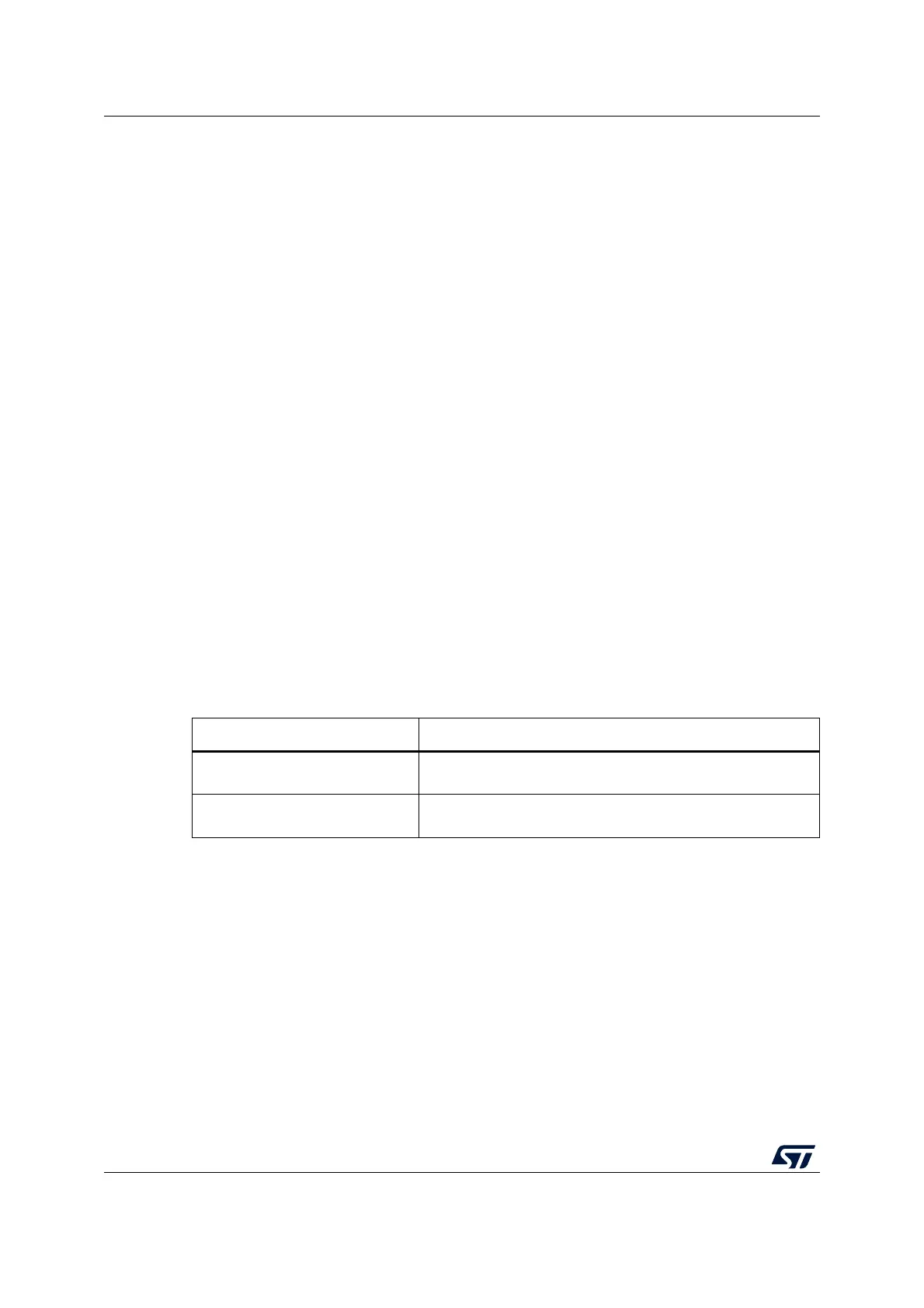
Table 4. CN4 states of the jumpers
Jumper state Description
Both CN4 jumpers ON
ST-LINK/V2-1 functions enabled for on-board programming
(default). See Section 6.3.3.
Both CN4 jumpers OFF
ST-LINK/V2-1 functions enabled for external CN6 connector
(SWD supported). See Section 6.3.4.