Hardware layout and configuration UM1974
18/85 UM1974 Rev 9
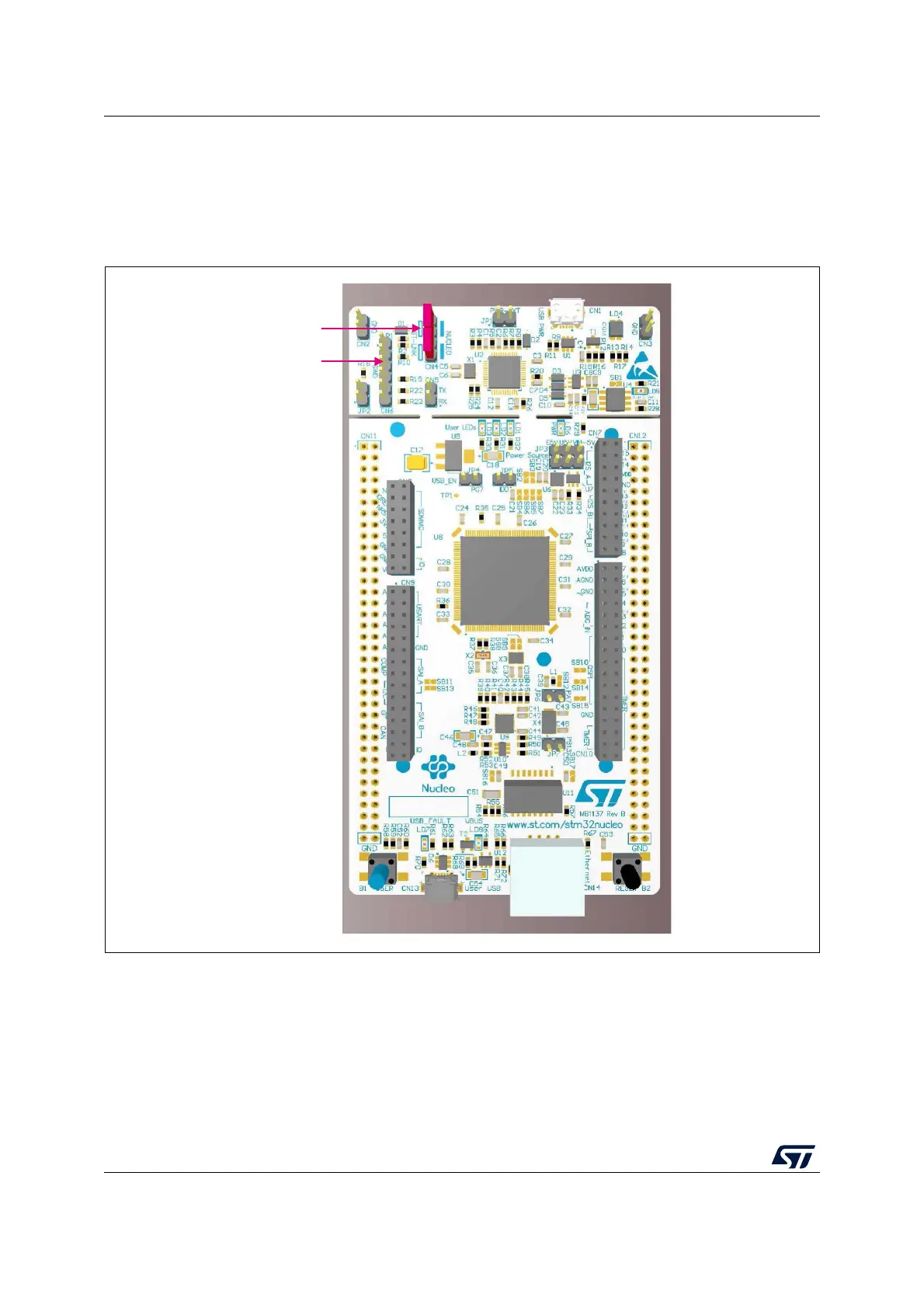
6.3.3 Using the ST-LINK/V2-1 to program and debug the on-board STM32
To program the on-board STM32, place the two jumpers marked in red on the connector
CN4, as shown in
Figure 9. The CN6 connector must not be used, since it might disturb the
communication with the STM32 microcontroller of the Nucleo-144 board.
Figure 9. Connecting the STM32 Nucleo-144 board to program the on-board STM32
MSv40065V3
CN4 jumpers ON
SWD connector
(CN6)