UM1974 Rev 9 31/85
UM1974 Hardware layout and configuration
84
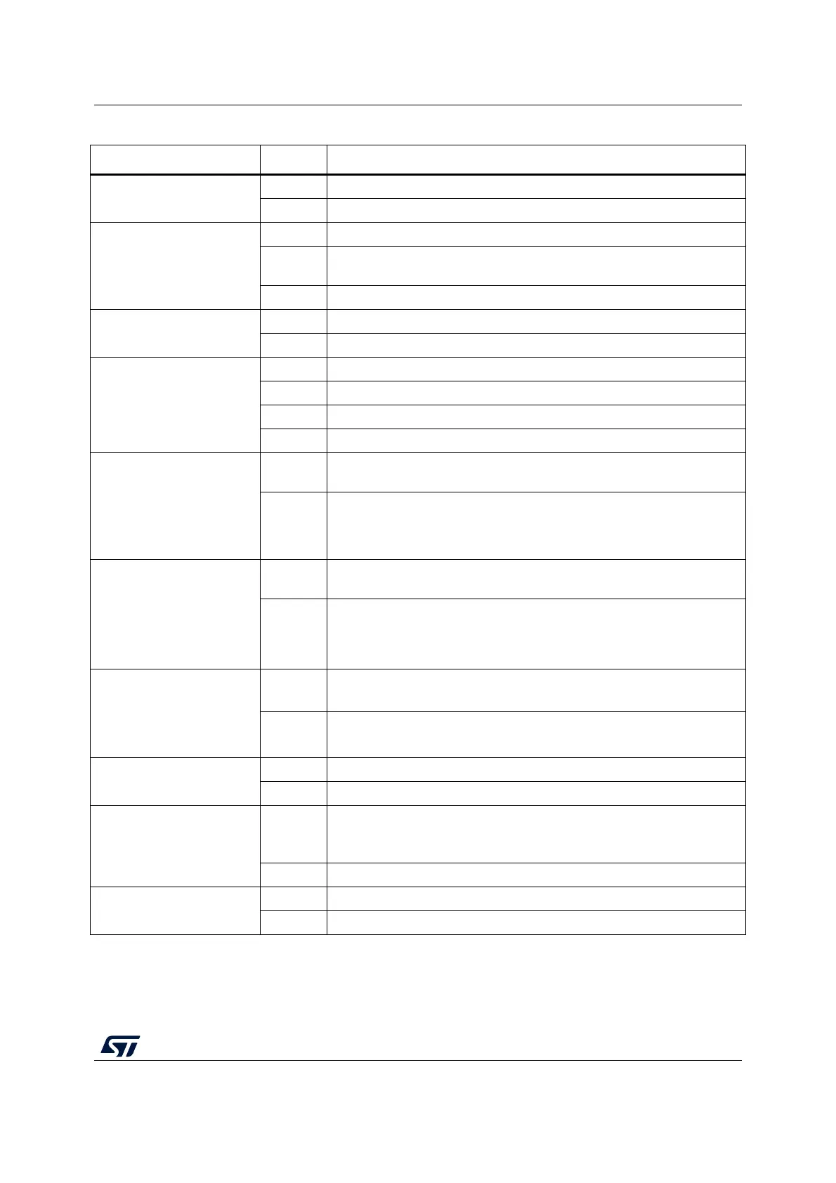
SB156 (V
BAT
)
ON V
BAT
pin of STM32 is connected to V
DD
.
OFF V
BAT
pin of STM32 is not connected to V
DD
.
SB173, SB180
(B1-USER)
ON, OFF B1 push-button is connected to PC13.
OFF,ON
B1 push-button is connected to PA0 (Set SB179 OFF if ST Zio connector
is used).
OFF,OFF B1 push-button is not connected.
SB179 (PA0)
ON PA0 is connected to ST Zio connector (Pin 29 of CN10)
OFF PA0 is not connected to ST Zio connector (Pin 29 of CN10)
SB142, SB152 (BOOT1,
Only for F2 and F4 Series)
OFF, OFF BOOT1 (PB2) function is not used.
ON, OFF BOOT1 (PB2) is pulled up.
OFF,ON BOOT1 (PB2) is pulled down.
ON, ON Forbidden
SB147,SB157 (A4 and A5)
Or SB167, SB171 (only for
NUCLEO-F303ZE)
Or SB140,SB150 (only for
NUCLEO-F412ZG and
NUCLEO-F413ZH)
ON
ADC_IN are connected to A4 and A5 (pin 9 and 11) on ST Zio connector
CN9. Thus SB138 and SB143 must be OFF.
OFF
ADC_IN are not connected to A4 and A5 (pin 9 and 11) on ST Zio
connector CN9.
SB138,SB143 (I2C on A4
and A5)
OFF
PB9 and PB8 (I
2
C) are not connected to A4 and A5 (pin 9 and 11) on
ST Zio connector CN9.
ON
PB9 and PB8 (I2C) are connected to A4 and A5 (pin 9 and 11) on ST Zio
connector CN9. Thus SB147 and SB157 (or SB167 and SB171 for
NUCLEO-F303ZE or SB140 and SB150 for NUCLEO-F412ZG and
NUCLEO-F413ZH) must be OFF.
RMII Signals
SB13 (PA1), SB164 (PC1),
SB160 (PA2), SB178 (PC4),
SB181 (PC5), SB182
(PG13), SB183 (PG11)
ON
These pins are used as RMII signals and connected to Ethernet PHY.
These ports must not be used on ST morpho or ST Zio connectors.
OFF
These pins are used as GPIOs on ST morpho connectors and not
connected to Ethernet PHY.
SB177 (Ethernet nRST)
ON NRST of STM32 is connected to Ethernet PHY (U9).
OFF NRST of STM32 is not connected to Ethernet PHY (U9).
USB signals:
SB186 (NUCLEO-F303ZE)
or SB187 (all other Nucleo
boards) (PG6)
ON
PG6 is connected to R70 to control USB D+ pull up (NUCLEO-F303ZE).
PG6 is connected to 5 V switch Enable (U12) to control V
BUS
or CN13 (All
other NUCLEO).
OFF This pin is used as GPIO on ST morpho connectors.
SB132 (PA12), SB133
(PA11)
ON These pins are used as D+ and D- on USB connector CN13.
OFF These pins are used as GPIOs on ST morpho connectors.
1. Default SBx state is shown in bold.
Table 12. Solder bridges (continued)
Bridge State
(1)
Description