77
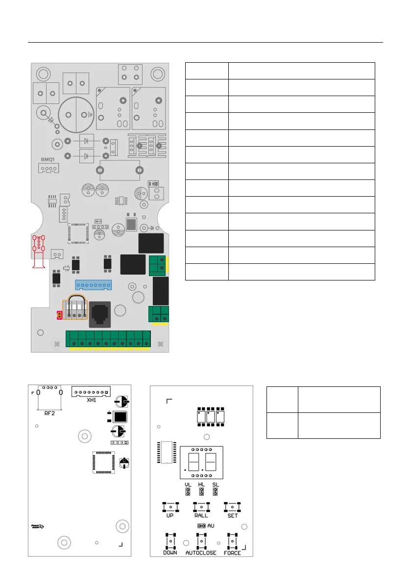
DESCRIPTION OF THE INPUTS / OUTPUTS OF THE CONTROL
XH1 Display board
terminal
RF2 Transmitter receiver
module terminal
XH01 DC24V Power input terminal
XH02 External function terminal
XH03 Gear motor power supply terminal
XH04 DC24V Input terminal
XH05 Electronic lock terminal
XH06 Relay module output terminal
BAT+ Lead-acid battery input terminal
RJ11 External wired wall control connection
WIFI1 WIFI control terminal
LED1 Courtesy light terminal
XH08 Safety terminal
XH09 Display board terminal
CLUTH Rear clutch protection terminal
RJ11
8
LED1
+12V
2
5
1
+
TP1
4
SD
CLUT
COM
COM
STOP
PE
FL
+24V
OPEN
CLOSE