Do you have a question about the STARCUS F35 and is the answer not in the manual?
Specifies the drive's purpose for industrial sectional doors and proper usage conditions.
Details essential safety rules for installation and operation by qualified personnel.
Emphasizes the necessity of installing safety covers and required safety devices.
Outlines crucial guidelines to prevent injury during installation.
Lists essential checks to prevent damage to the drive during installation.
Specifies the required minimum tensile strength for mounting screws.
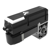
Lists the provided accessories for mounting the drive unit.
Details the process for installing the console assembly onto the door shaft.
Summarizes key checks for fasteners, wiring, and safety devices after installation.
Explains how to activate and use the automatic door closing feature.
Describes how to adjust the force levels for door operation.
Details how to view the number of operation cycles performed by the drive.
Provides instructions for restoring the controller to its default factory settings.
Guides on setting the open and close travel limits for the door.
Covers general function settings and wired push button modes.
Adjusts the sensitivity for reversing the door based on obstacles.
Allows precise fine-tuning of the door's fully open position.
Allows precise fine-tuning of the door's fully closed position.
Configures door closing and opening speeds and deceleration profiles.
Sets the distance over which the door slows down before reaching its limit.
Configures the door's soft stop behavior during operation.
Sets the timer and conditions for the automatic door closing function.
Enables and configures safety sensors like infrared beams and light curtains.
Configures the identification of built-in infrared or light curtain sensors.
Configures terminals for additional functions.
Sets a specific height for partial door opening.
Configures the function of the PB (Push Button) port.
Manages the electronic lock mechanism and its operation.
Controls the behavior of warning lights during door operation.
Configures the functionality of the XH06 relay output module.
Configures the safety device port for various sensors.
Sets the delay time and warning behavior for the courtesy light.
Configures the cycle counting for maintenance alarms.
Allows checking the remaining cycles before a maintenance alarm is triggered.
Sets the direction of rotation for the gear motor.
Details the connections and functions of the XHO2 output terminal.
Details the connections and functions of the XH05 electronic lock output terminal.
Details the connections and functions of the XH06 relay output module.
Describes connections for wicket door and electrical safety edge sensors.
Describes connections for optical safety edge and infrared photo eye sensors.
Details safety terminal V1 connections for infrared sensors and light curtains.
Details safety terminal V2 connections for infrared sensors, light curtains, and alarm systems.
Provides instructions for installing optical edge sensors and their components.
Explains the wiring process for connecting optical edge sensors.
Outlines regular inspection steps for maintaining optical edge sensor performance.