82
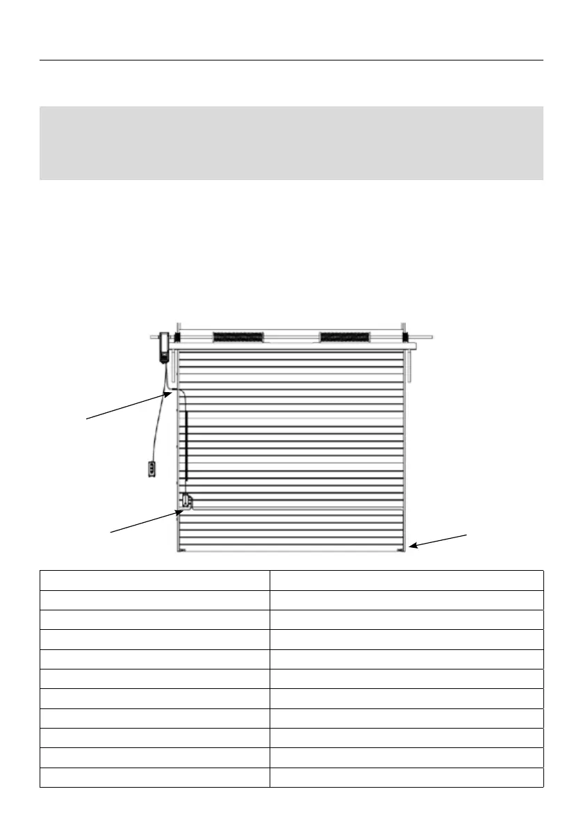
1. According to the installation position of the motor, x the safety junction box on one
side of the door. The transmitting and receiving ends of the optical edge sensors are
xed to the two ends of the door rubber strip by rubber plugs.
2. The optical edge sensors signal line is connected to the safety control box, and the
safety junction box is connected to the motor through a spring wire.
Note: The spring wire needs to be xed on the side of the door frame with a spring wire
bracket. Please see the following diagram for specic installation:
When connecting the optical edge sensors to the motor for use Need to remove the 8.2K
resistor on the control box rst. Follow the instructions below to access the control box
interface, and set the function to 6.8, the optical edge sensors can be used normally.
Voltage
DC 12-24V
Power Consumption
Below 6mA
Detection Distance
0.5m~10m
Error distance
Less Than 10% of Detection Distance
Detect Object
Translucent/Non-transparent Objects
Physical Dimension
37*13mm
Line Length of Transmission Interface
10m
Line length of receiving Interface
1m
Operating Temperature
-20℃~75℃
Waterproof Level
IP67
Weight
About 0.17Kg
DESCRIPTION OF THE INPUTS / OUTPUTS OF THE CONTROL
 Loading...