Static Solutions CT-8900 Combo Tester Instructions 1/15/2015
15
Door Relay
Units that are ordered with the a door-opening relay option will be equipped with two pigtail wires found on the right side of the unit.
There are two male bayonet type plugs attached to these wires. There are two unwired female jacks attached to these male plugs,
which can be attached to the open/close schematics on the door/bell circuit board (connected to the door mechanism). The relay in
the CT-8900 is a single throw, low voltage single pole normally open relay. When the user passes a test, the relay is activated and
remains closed for about 3 – 5 seconds after the user releases the test button. Units manufactured after 1/30/2006 have an
activation time adjust trimpot in them which can be used to adjust the door open time from about 1 – 9 seconds (see photograph
below).
The relay is rated .5 amps at 24 volts. It is illegal to introduce voltages greater than 24V into this unit, since shock hazards coluld
possibly occur. Please refer to the schematics of a footplate door opening mechanism. Substitute the two wire door wires for the
two-wire connection of the door foot-switch or hand-switch. The door in a facility has a second relay, usually of a higher voltage of
110 or 220VAC that allows voltage into the door electrical motor that opens and closes a door. This relay can be activated by a
press button, a proximity sensor, or a floor switch as in a super market. When a person passes the combo meter strap tests, the low
voltage relay in the combo meter is closed thus allowing current to pass into the higher voltage door relay and activate the motor in
the door. When the low voltage relay in the meter opens the reverse happens – the high voltage relay in the door is opened thus
stopping the door current, and the door closes.
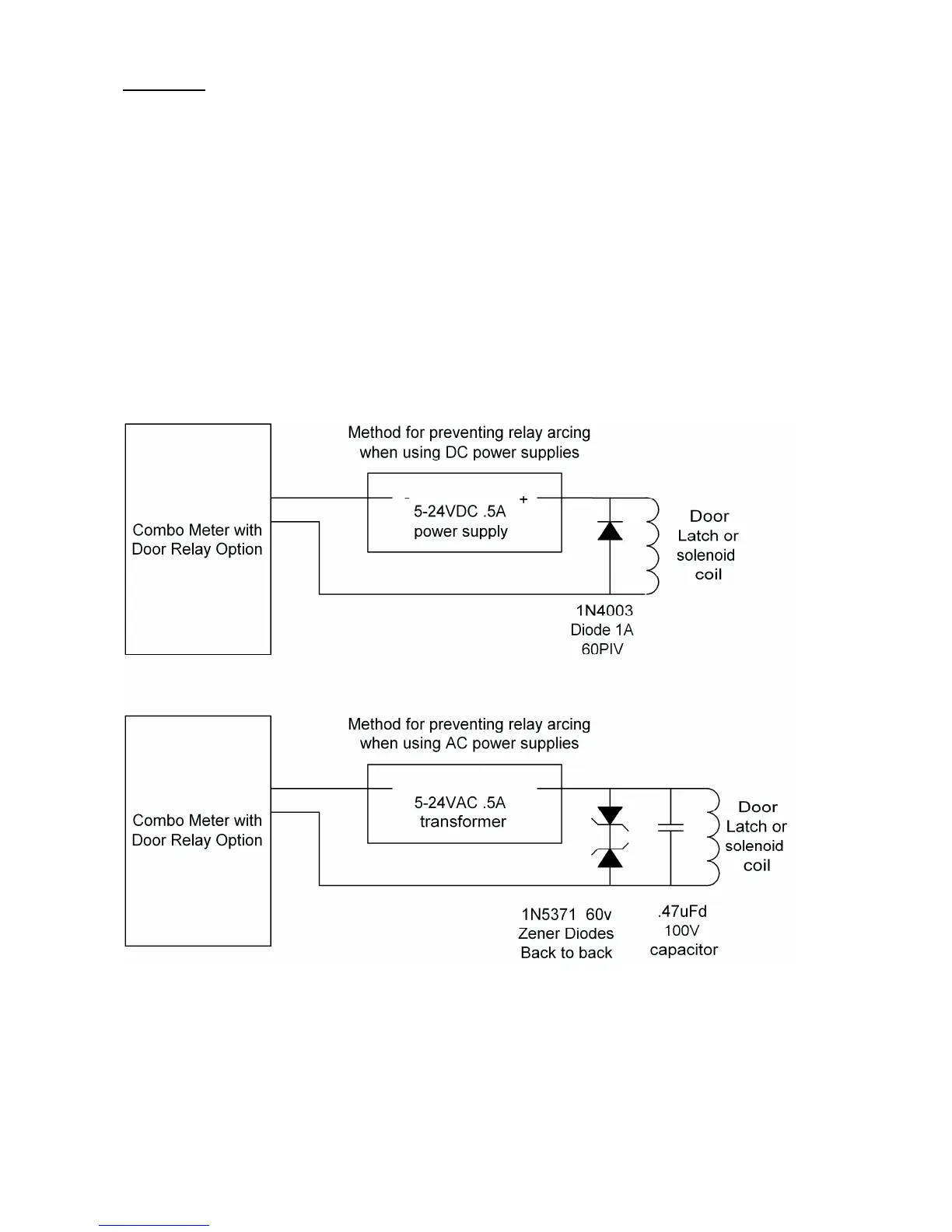
If the door relay contact is in series with a high current inductive load door latch such as a large solenoid or electromagnet, then
arcing can develop across the relay contact when the contact breaks the circuit, and shorten the relay life.
To prevent relay contact arcing if the contact current is DC, then a diode (such as a1N4003 or 1N4004) across the coil leads, with
cathode (band side) on the positive lead, may be wired across the contacts. The diode should have a PIV (peak inverse voltage)
rating of at least twice the DC voltage.
To prevent relay contact arcing if the contact current is AC, then two zener diodes back to back (band to band) may be wired across
the coil leads. The zener voltage should be at least twice the AC voltage. If running 24VAC (30VAC open load?), use two 60 volt
1N5371B zeners.