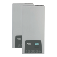
Frequency limits
The following frequency limits can be changed:
n Upper disconnection value
n Lower disconnection value (Fig. left)
n Derating switch-on threshold (because frequency is too high)
n Frequency threshold when switching on again
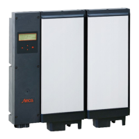
Voltage limits ø (average value)
The following voltage limits can be changed:
n Upper disconnection value
1)
(Fig. left)
n Lower disconnection value
1)
1)
The disconnection value relates to the average value of the
voltage.
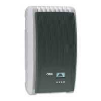
Reactive power characteristic curve
Overview
The reactive power characteristic curve must be set during initial
commissioning if this is prescribed for the previously selected
country. The following applies:
n 3 characteristic curves are available for selection (Fig. left):
– Default. char. curve (pre-defined)
– Enter char. curve (manually adjustable)
– Char. curve cos
φ = 1 (pre-defined)
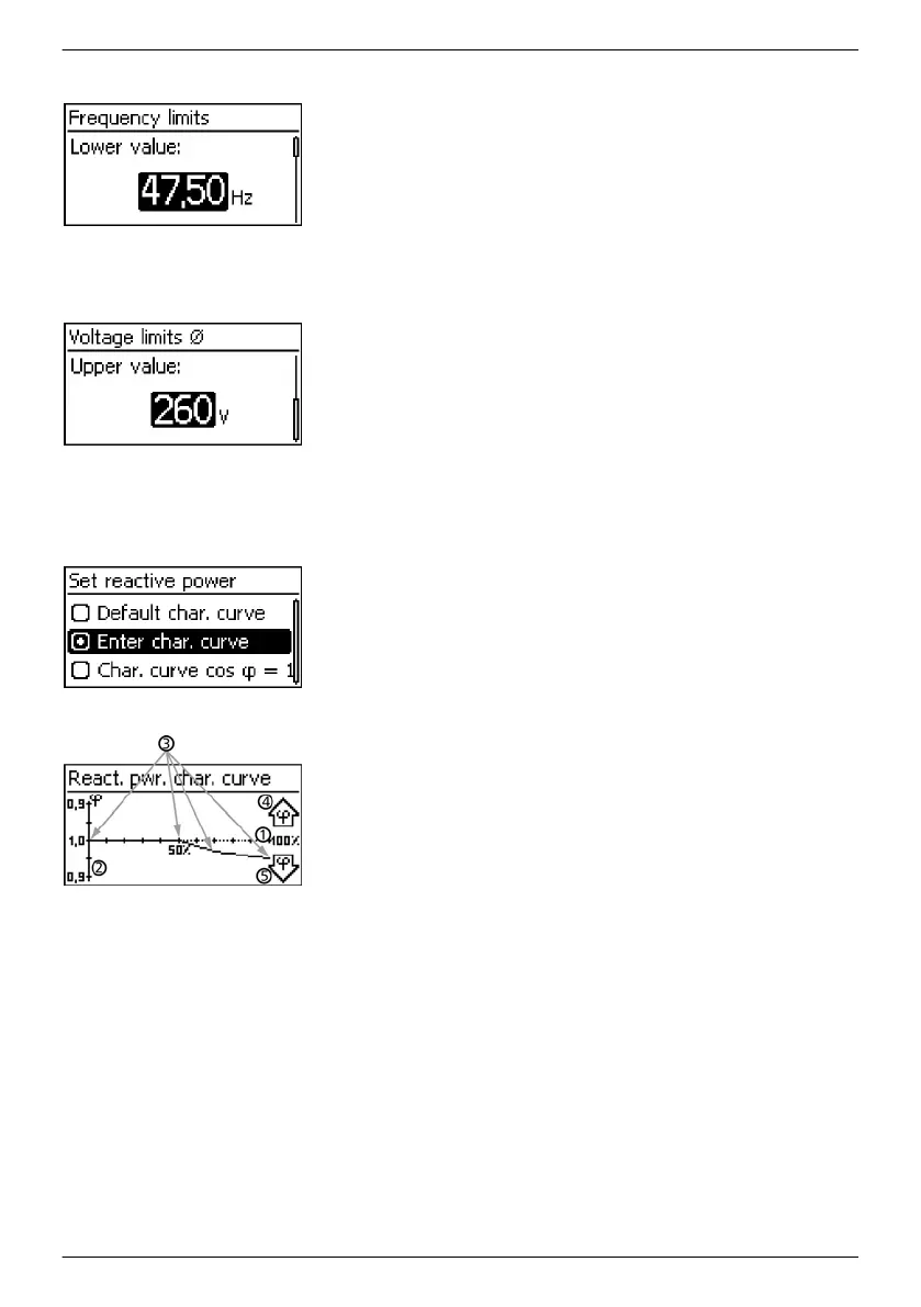
n After configuration, the characteristic curve is displayed as a
graph (example in Fig. left).
① x-axis, output power P in %
② y-axis, phase shift cos φ
③ Nodes (in example: 4 nodes)
④ Arrow symbol Overexcitation
⑤ Arrow symbol Underexcitation
EN
747,431 | Z09 | 2015-09-30
24