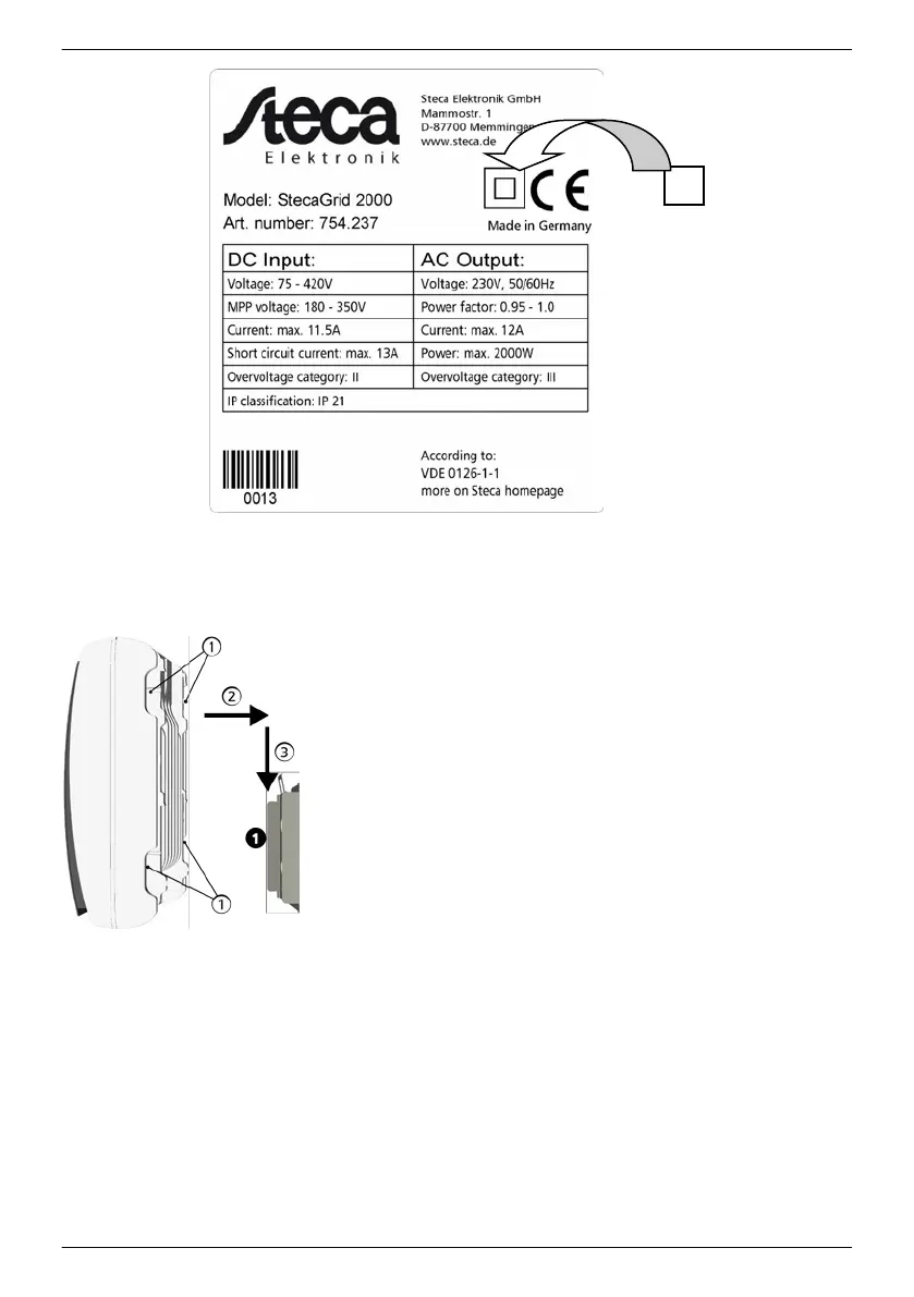
Fig. 11: Position of the sticker for covering the Protection Class II symbol
Attaching the inverter on the mounting plate
1. Grasp inverter on the grip recesses ①
(coolcept) or on the
perimeter edge (coolcept-x), fit it onto the mounting plate ➊
so that it is centred ② and lightly press it on (see the example
in the fig. on the left).
2. Lower inverter ③, until the securing sheet metal element of
the mounting plate audibly locks in place. In this process, the
hooks on the rear of the inverter must be guided above the
catches on the mounting plate.
3. The inverter must now be firmly seated on the mounting plate
and it can no longer be lifted (upwards).
—————————————————————————
Note
How to remove the inverter from the mounting plate is described
under
Ä
4.9, S. 48 .
—————————————————————————
4.3 Prepare AC connection
4.3.1
Miniature circuit breaker
Information on the required line circuit breaker and the cables to be used between the inverter and
the line circuit breaker is provided in
Ä
9.2, p. 82
EN
747,431 | Z09 | 2015-09-30
36