3 Structure and function
3.1
Housing
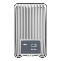
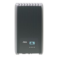
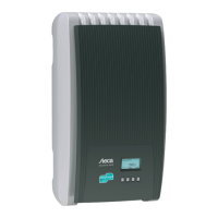
3.1.1 coolcept
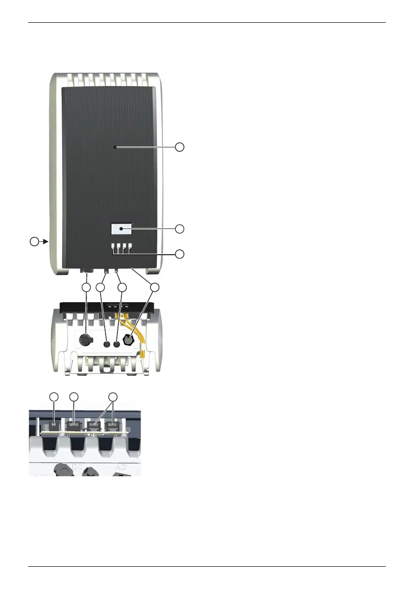
①
Hood
②
Display (monochrome, 128 x 64 pixels)
③
Rating plate, serial number, warnings
④
Operating buttons: ESC, r, s, SET (from left to
right)
⑤
1x AC connection
⑥
1x DC connection Minus (−) for solar modules
(Phoenix Contact SUNCLIX, safe-touch)
⑦
1x DC connection Plus (+) for solar modules
(Phoenix Contact SUNCLIX, safe to touch)
⑧
DC load-break switch (disconnects plus and
minus input simultaneously)
⑨
2 x RJ45 sockets (RS485 bus)
⑩
1x RJ45 socket (Ethernet)
⑪
1x RJ10 socket (Modbus RTU)
The casing components are described in detail below.
EN
747,431 | Z09 | 2015-09-30
14