Technical details
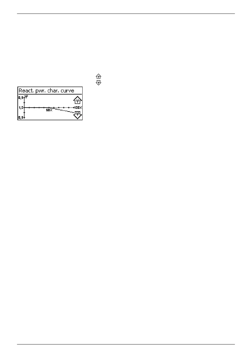
n Each characteristic curve is defined by 2 to 8 nodes.
n A node is defined by the output power P of the inverter (x-axis)
and the associated phase shift (y-axis).
n The phase shift can be set over a range of 0.95 (overexcitation)
through 1.00 (no phase shift) to 0.95 (underexcitation).
n The type of phase shift is shown in the graph using arrow
symbols defined as follows (defined from the point of view of
the inverter):
Overexcitation, inductive
Underexcitation, capacitive
n The 3 characteristic curves available for selection have the
following properties:
‘Default. char. curve’ : pre-defined according to the selected
country (example in Fig. left).
‘Char. curve
φ = 1’
: pre-defined with cos φ = constantly 1.00.
This characteristic curve must be selected if no reactive power
control is to be performed on the device.
‘Enter char. curve’ : The number of nodes and their x/y values
can be configured. Exceptions: the first node is always located
at x (P %) = 0 % and the last node is always located at
x (P %) = 100 %.
All parameters
Service technicians can use this menu item for changing additional
MSD parameters.
3.4 Cooling
The internal temperature control system prevents excessive operating temperatures. When the
internal temperature is too high, the inverter adjusts the power consumption from the solar
modules to reduce the heat dissipation and operating temperature.
The inverter is convection cooled via fins on the front and rear side. A maintenance-free fan
circulates the heat within the closed casing evenly over the entire surface of the casing.
3.5
Grid monitoring
The inverter constantly monitors the mains grid parameters while feeding the grid. If the grid
deviates from the legally prescribed specifications then the inverter automatically switches off.
When the grid conforms to the legally prescribed specifications then the inverter automatically
switches on again.
3.6 Data communication
The device has the following communication interfaces:
n 1x RJ45 socket (Ethernet for TCP/IP network) for communication, e. g. with a central data server
n 2x RJ45 sockets (RS485 bus) for communication with external devices, e. g. a data logger
n 1x RJ10 socket (Modbus RTU) for communication e. g. with an external energy counter
EN
747,431 | Z09 | 2015-09-30
25