Tech Support: www.steppir.com/support Tel: 425.891.6134 support@steppir.com
Page 57
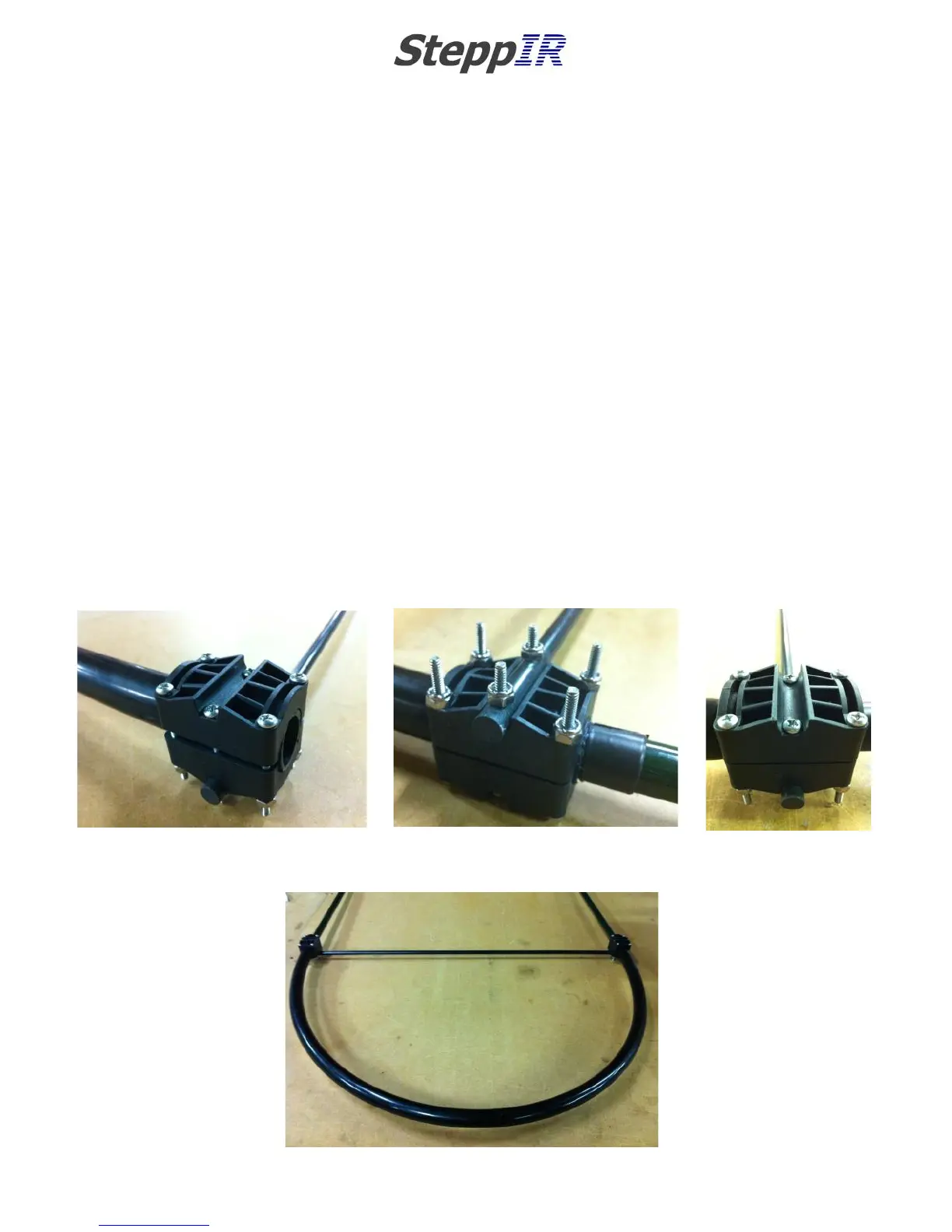
Mounting the fiberglass spreaders
Attach the black fiberglass sweep spreaders (PN 10-1503-21) to the sweep couplers. There is a con-
cave mounting area on each side of the plastic couplers. Position the fiberglass spreader so that the
holes align with the couplers as shown in figure 6.13. When installing the fiberglass spreader, you will
want the spreader to be underneath the plastic coupler as shown in figure 6.14. The loop has been
turned upside down in this picture so you can see the detail. The spreaders will be longer than the
couplers on each side of the loop as shown in figure 6.15. This is done on purpose to ensure plenty of
fiberglass material is on each side of the screw.
Insert #10 x 2” pan-head machine screw (PN 60-0156) through each of the coupler halves and the fi-
berglass rod. This screw must be placed so that the Philips head of the machine screw is seated inside
the concave groove on the top coupler as shown in figure 6.15 and the Nylock nut (PN 60-0014) is
secured against the fiberglass material as shown in figure 6.14. The machine screws are longer than
normal by design so that you can get the nut on in the initial stages of the process.
Tighten the Nylock nuts firmly. Be sure to use anti-seize on these screws or they very likely will gall
and have to be replaced.
CHAPTER SIX
SECTION 6.1
EST PREPARATION (continued)
MOUNT THE FIBERGLASS SPREADERS ON THE SWEEP COUPLERS
FIG. 6.15
FIG. 6.14
FIG. 6.13
FIG. 6.16