Tech Support: www.steppir.com/support Tel: 425.891.6134 support@steppir.com
Page 56
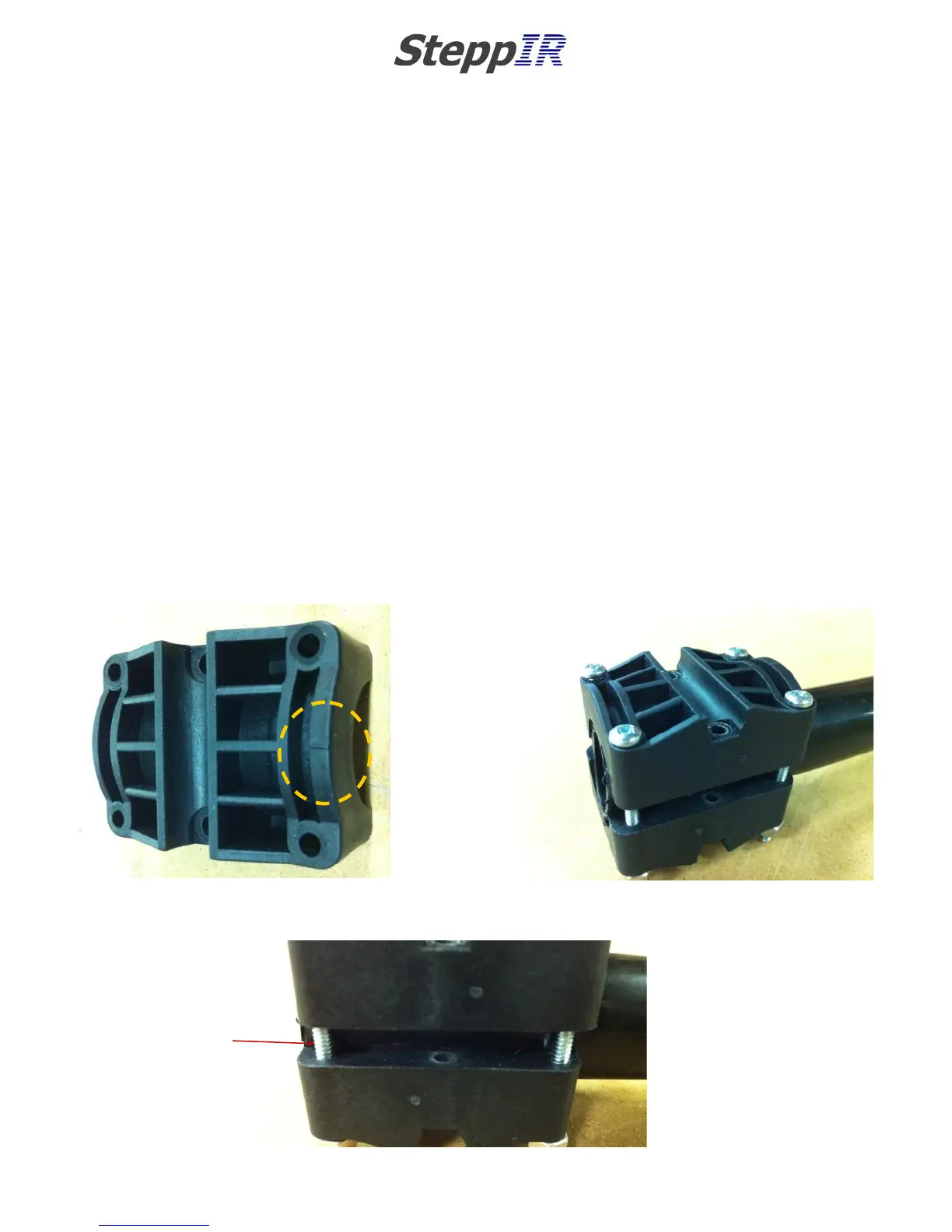
Attach the sweep couplers to the plastic sweep tubes
Each of the sweep coupler halves will have a notch in the mold on one side. It is critical that these
notches are pointing towards the sweeps or they will not work properly. See figure 6.10 for the location
of the mark. Be certain that each half of the coupler has the mark facing the sweep tube!
Place the coupler halves on the end of the plastic sweep tubing as shown in figure 6.11.
Insert the four 60-0156 #6 x 2” screws. Place the screws so that the threaded portion of the screw is
facing downward. BE SURE THAT THE DRAIN HOLES FOR THE PLASTIC SWEEP TUBE ARE POINTING
DOWNWARD BEFORE INSTALLING THE COUPLERS. Apply anti-seize to the threads and place the Ny-
lock nuts on. Tighten nuts until there is approximately a 0.25” gap between the two coupler halves as
shown in figure 6.12. Repeat for other side of sweep tube.
The couplers are designed to re-form the plastic sweeps to lock them in place – do not be alarmed if
there is a need to exert a fair amount of force when tightening the screws, as this is normal.
These screws will be completely tightened later, tightening to this point provides a framework for the
ensuing steps.
Figure 1.07
0.25” GAP
GAP
CHAPTER SIX
SECTION 6.1
EST PREPARATION (continued)
ATTACH THE SWEEP COUPLERS TO THE SWEEP TUBES
FIG. 6.10
FIG. 6.11
FIG. 6.12