22
1
2
3
4
5
6
-5 0 5 10 15 20
Quelleneintrittstemperatur [°C]
Temperaturdifferenz [K]
Sole - HV 35°C
Sole - HV 50°C
g/cm
1,130
1,120
1,110
1,100
1,090
1,080
1,070
1,060
1,050
1,040
1,030
1,020
1,010
1,000
0,990
0,980
O = Frostsicherheit
–20 –10 0 10 20 30
°C
40 50 60 70
0 VOL-% = Wasser
40 VOL-% = (-25°C)
37 VOL-% = (-23°C)
28 VOL-% = (-15°C)
20 VOL-% = (-10°C)
44 VOL-% = (-30°C)
52 VOL-% = (-40°C)
60 VOL-% = (-50°C)
100 VOL-% = Ethylenglykol
R
3
2.9.3.2 Connection and filling with brine
Prior to connecting the heat pump, check the
heat source circuit for possible leaks, and flush
thoroughly.
After filling the system with brine, and prior
to commissioning, open the fill & drain valve
(item 17, Fig. 1), until brine runs out of it. No
water must remain in the pipe run to the fill &
drain valve.
Calculate the volume of the heat source circuit.
You can obtain the brine volume inside the
heat pump from the following table.
Heat pump Brine volume
WPF 5 (S) 5,84 l
WPF 7 (S) 6,45 l
WPF 10 (S) 7,06 l
WPF 13 7,06 l
WPF 16 7,06 l
The overall volume equals that of the required
brine, which should be mixed from 33 % (vol.)
pure ethylene glycol and 67 % (vol.) water.
Mixing ratio:
1 unit pure ethylene glycol with
2 units water (max. chloride contents in the
water = 300 ppm), then fill mixture into the
system.
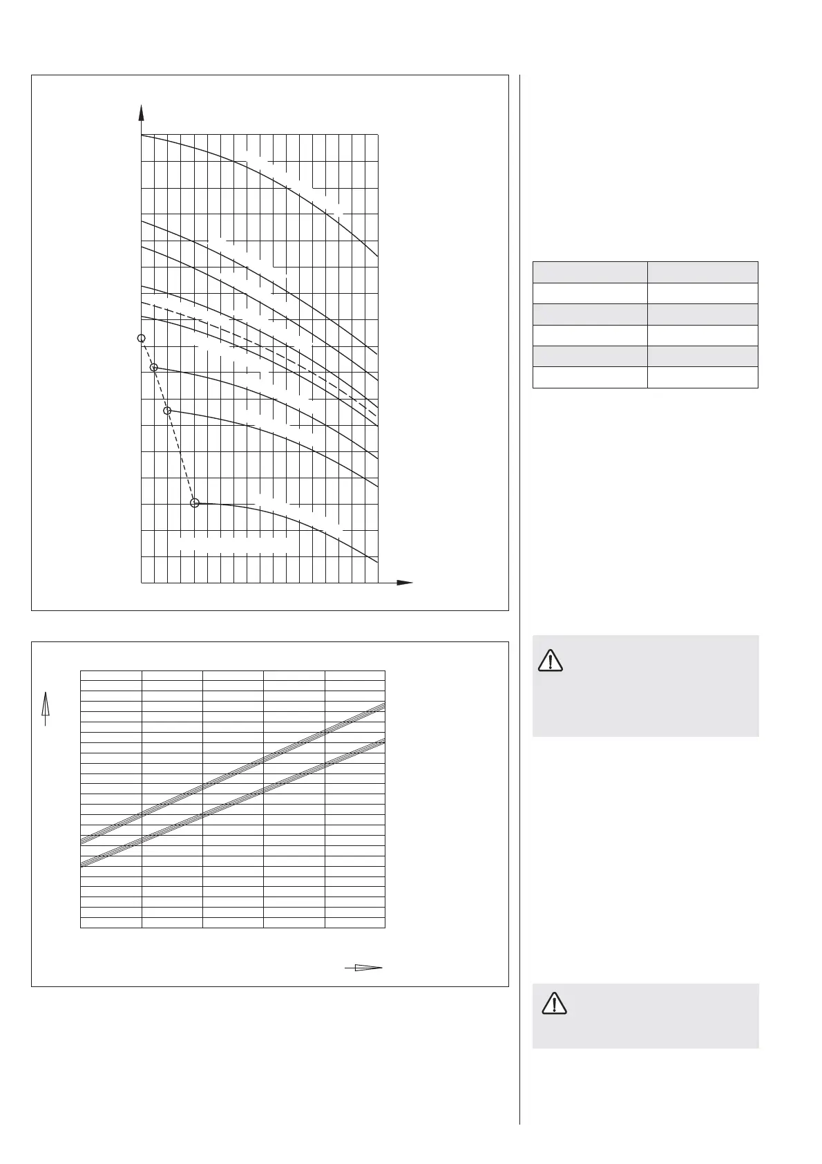
Checking the brine concentration:
Determine the density of the ethylene glycol
water mixture (e.g. with a hydrometer). Using
the actual density and temperature, you can
check the current concentration in the diagram
(Fig. 7).
The details quoted refer to ethylene
gylcol. When using propylene glycol
and the Stiebel Etron process medium as
ready-mixed solution (part no 185472),
these details will be slightly different (see
specification).
To prevent the transmission of noise, connect
the heat source circuits to the heat pump with
flexible pressure hoses
(part no. see section 2.2).
2.9.3.3 Volume flow control
(to be implemented during heat pump com-
missioning)
Measure the flow and return temperatures
of the heat source. For this, determine the
temperature difference by measuring the
temperature under the thermal insulation on
both flow and return pipes of the heat pump.
The diagram (Fig. 8) shows the temperature
spread at the rated volume flow.
You can check the source inlet tem-
perature on the WPMi display under
system parameter INFO TEMP.
Brine concentration
Temperature spread at rated volume flow
Density U of ethylene glycol-water mixtures
with different concentration levels
Brine - Flow temp. 35°C
Brine - Flow temp. 50°C
Inlet temperature of source medium [°C]
Temperature difference [K]
Water
Frostprotection
C26_03_01_0143
Fig. 8
Fig. 7
26_03_01_0092C

 Loading...


