25
L N R RC L L’ N L N PE
S
ON
KS
Kühlen
1 2 3 4 5 6 7 8 9 10 11 12 13
B1
B1
L N R RC L L’ N L N PE
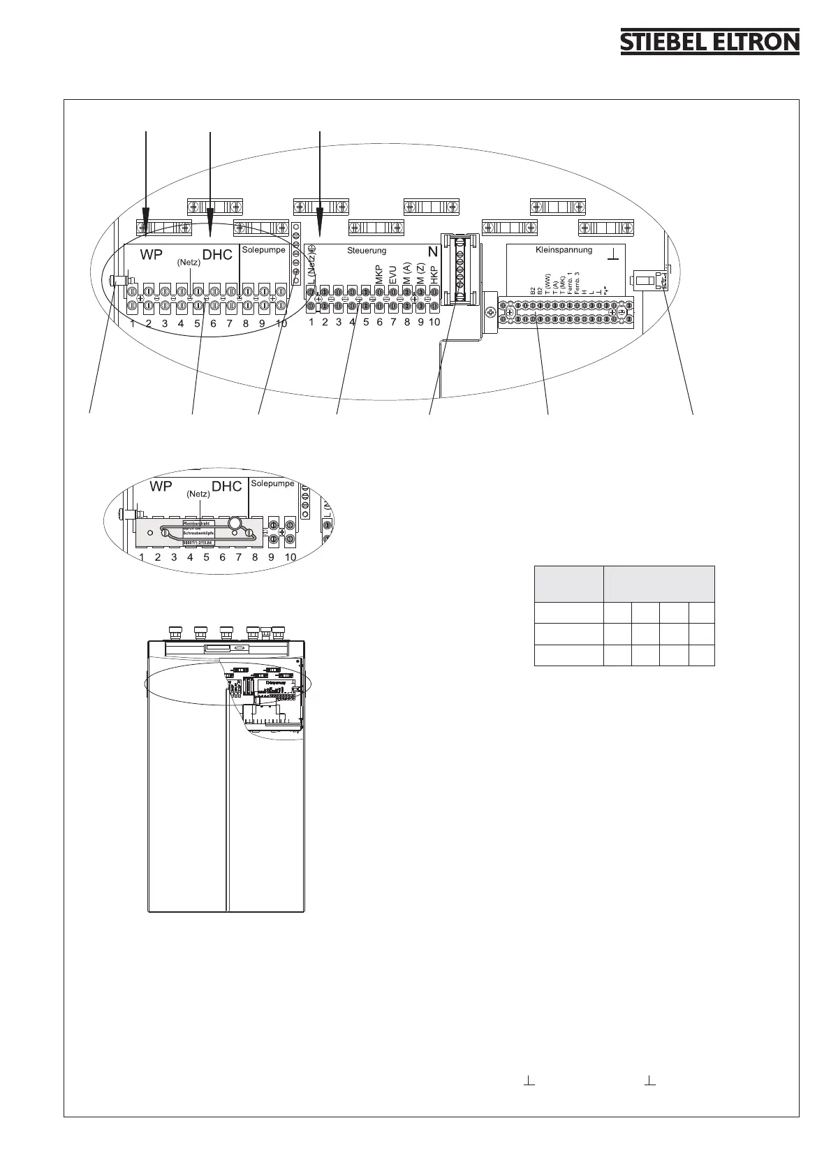
Fig. 9
X3 Mains supply
HP Heat pump (compressor)
L, N, PE
R, RC, N, PE (only in conjunction with WPAB)
DHC Supplementary heater
L, L´, N, PE
Terminal
rating
Terminal allocation
3,0 kW L N PE
3,2 kW L´ N PE
6,2 kW L L´ N PE
Solepumpe
L, N, PE
X4 Terminal - control
Netzanschluss: L, N, PE
Outputs:
S Control output for the WPAB
ON Compressor signal
KS Brine pump signal
Kühlen Cooling mode
MKP Mixer circuit pump and N, PE
M(A) Mixer OPEN
M(Z) Mixer CLOSE
HKP Heating circuit pump and N, PE
Control inputs:
EVU Power Supply Company Signal
X2 Terminal LV
B1 Temperature sensor HP flow
B1 Temperature sensor HP flow
B2 Temperature sensor HP return
B2 Temperature sensor HP return
T(WW) DHW temperature sensor and earth
T(A) Outside temperature sensor and earth
T(MK) Mixer circuit temperature sensor and earth
Fernb. 1 Remote control 1
Fernb. 3 Remote control 3
H BUS High
L Bus Low
BUS Ground
“ + “ BUS “ + “
X26 (earth)X2
NX4PEX3
PE
Wiring diagram WPF 5 S / 7 S / 10 S (Singlephase)
C26_03_01_0254
1/N/PE~230/50
2,5 - 4 mm
2
2/N/PE~230/50
4 - 6 mm
2
1/N/PE~230/50
1,5 mm
2
Provide separate fuses for the three
power circuits HP, supplementary heater
and control.

 Loading...


