39
Setting ON
DHW heating will be terminated and the set
DHW temperature is overwritten with the
actual DHW temperature, as soon as the heat
pump is shut down in DHW mode via the HP
sensor or via the hot gas temperature limit
(130 °C). This operating mode saves energy,
as the DHW is exclusively heated with the heat
pump.
DHW HYSTERESIS
This determines the switching hysteresis for
the DHW operation.
– Starting DHW heating at the DHW set
value minus the hysteresis value.
DHW CORRECTION
The DHW temperature is measured in the
lower third of the cylinder. The DHW outlet
temperature is approx. 3 K higher than the
measured temperature. This deviation is
corrected and can be calibrated, if required.
PASTEURISATION
The DHW cylinder is heated daily at 01:00 h to
60 °C, if pasteurisation has been enabled.
CNTRL DYNAMIC
Setting range 0 to 30
The selected control dynamic is a measure
of the switching gap between individual
compressors and the backup heating stages.
Normally, the selected response time
should operate sufficiently fast and without
oscillation.
Heating systems which respond quickly
require a lower value, whilst very slow
reacting systems require you to set a higher
value.
COMPRESSOR IDLE TIME
After a heat pump has been switched OFF,
an idle time is set as compressor protection.
The default idle time of 20 minutes should
generally not be reduced. Where a reduction
is required because of adjustments or repair
work, reset the idle time again to 20 minutes
after completing the necessary work.
COMP DLAY CNTR
Residual idle time
Pressing PRG enables you to scan the
compressor idle time.
SINGLE PHASE
For single phase equipment, this parameter
must always be set to ON.
QUICK START
During commissioning, you can test the heat
pump function by triggering a heat pump
quick start. When this parameter is started,
OFF appears at the bottom of the display.
Pressing PRG initiates a quick start. The
respective pumps are started after the heat
pump start. The value 60 is visibly counted
down to 0 on the display; then the display
shows ON.
After that, the heat pump and the associated
buffer primary pump are switched ON.
You terminate this function by pressing PRG
or by closing the control flap. OFF is displayed
again.
RELAY TEST
Pressing PRG and continuing to turn the rotary
selector allows you to control the WPMi relay
outputs individually. The individual outputs are
displayed as plain text.
LCD TEST
Pressing PRG once initiates a LCD test. All
display elements are displayed in sequence.
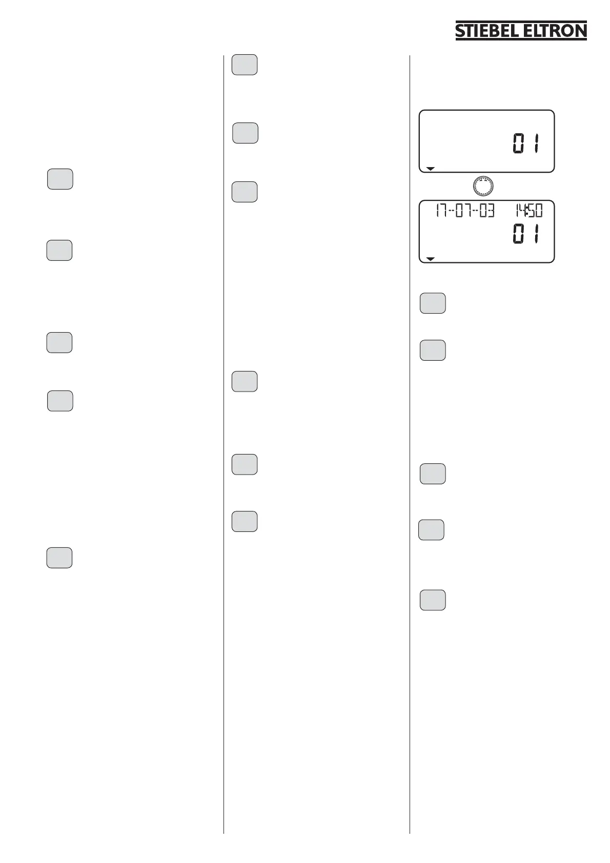
FAULT LIST
Pressing PRG displays the first fault code. The
fault is described in plain text at the top of the
display, the bottom shows the fault number.
Continuing to turn the rotary selector still
displays fault 1. As additional information,
the display shows the day, month and year
together with the relevant time, when the fault
occurred.
In total, 20 faults can be displayed. You can
reset the fault list via a hardware reset.
Example:
The high pressure switch has responded on
the 17.07.03 at 14:50 h representing the latest
fault in the heat pump.
SOFTWARE WPMiI
Display of the current software issue.
ANALYSIS
The bottom of the display shows the enabled
stages.
The two-digit display shows the internal
controller calculation. A stage will be switched
every time the counter has counted down
to zero. This calculation depends on the
controller dynamic and the control deviation.
For this, see controller dynamic.
DIAGNOSTIC (WPMi)
Pressing PRG indicates, whether an FEK is
connected.
DIAGNOSTIC (WPMiw)
Pressing PRG indicates whether an FEK is
connected and which type of heat pump is
connected.
HEAT P RESET
You can reset the heat pump in case of faults.
That fault is reset by pressing PRG and setting
the system to ON, followed by repeatedly
pressing PRG. The compressor starts again.
The fault remains in the fault list.
28
29
30
31
33
35
36
37
38
39
40
41
42
32
34
41
HP SENSOR MAX

 Loading...


