OPERATION
Menu structure
www.stiebel-eltron.com WPM 3| 21
MAXIMUM FLOW TEMPERATURE
Maximum heat pump flow temperature for heating
This setting limits the flow temperature of the heat pump and the
electric emergency/booster heater in heating mode.
FIXED VALUE OPERATION
The heat pump return is regulated to the set fixed value. The
time switch program will then be ignored. The various positions
of the program selector will then only affect the mixer circuit (if
installed). When the program selector is set to standby and a fixed
value has been selected, frost protection mode is activated and
the compressor is switched off. Summer logic is disabled with
fixed value control. This means that the heating circuit pump is
not switched off for the direct heating circuit.
HEATING CIRCUIT OPTIMAL
When an Uponor DEM-WP module is connected, the heating curve
is dynamically optimised for the heat demand of individual rooms.
This involves modifying the preset heating curve by up to 50%
of its original value.
The parameter HEATINGCIRCUITOPTIMAL is only displayed when
the buffer operation parameter is set to “OFF” and neither a mixer
sensor nor an FE7 remote control are connected.
The parameter HEATINGCIRCUITOPTIMAL can be set to “ON” or
“OFF”. The default value is “OFF”.
This parameter may only be set to “ON” when an Uponor DEM WP
module is connected.
This function is only active in comfort mode, ECO mode and pro-
grammed operation.
FROST PROTECTION
To protect the heating system from frost, the heating circuit pumps
start at the selected frost protection temperature; the reverse hys-
teresis is 1K.
REMOTE CONTROL FE7
This menu item is only displayed when the FE7 remote control is
connected.
HEATING CIRC PRESELECTION
The FE7 remote control can be selected for both heating circuits.
This parameter lets you choose which heating circuit the remote
control is to act on. The actual room temperature can be called
up under INFO / SYSTEM / ROOM TEMPERATURE.
ROOM INFLUENCE
See description in chapter “HEATING/ HEATING CIRCUIT 1 and
HEATING CIRCUIT 2/ ROOM INFLUENCE”.
ROOM CORRECTION
You can use this parameter to correct the measured room tem-
perature.
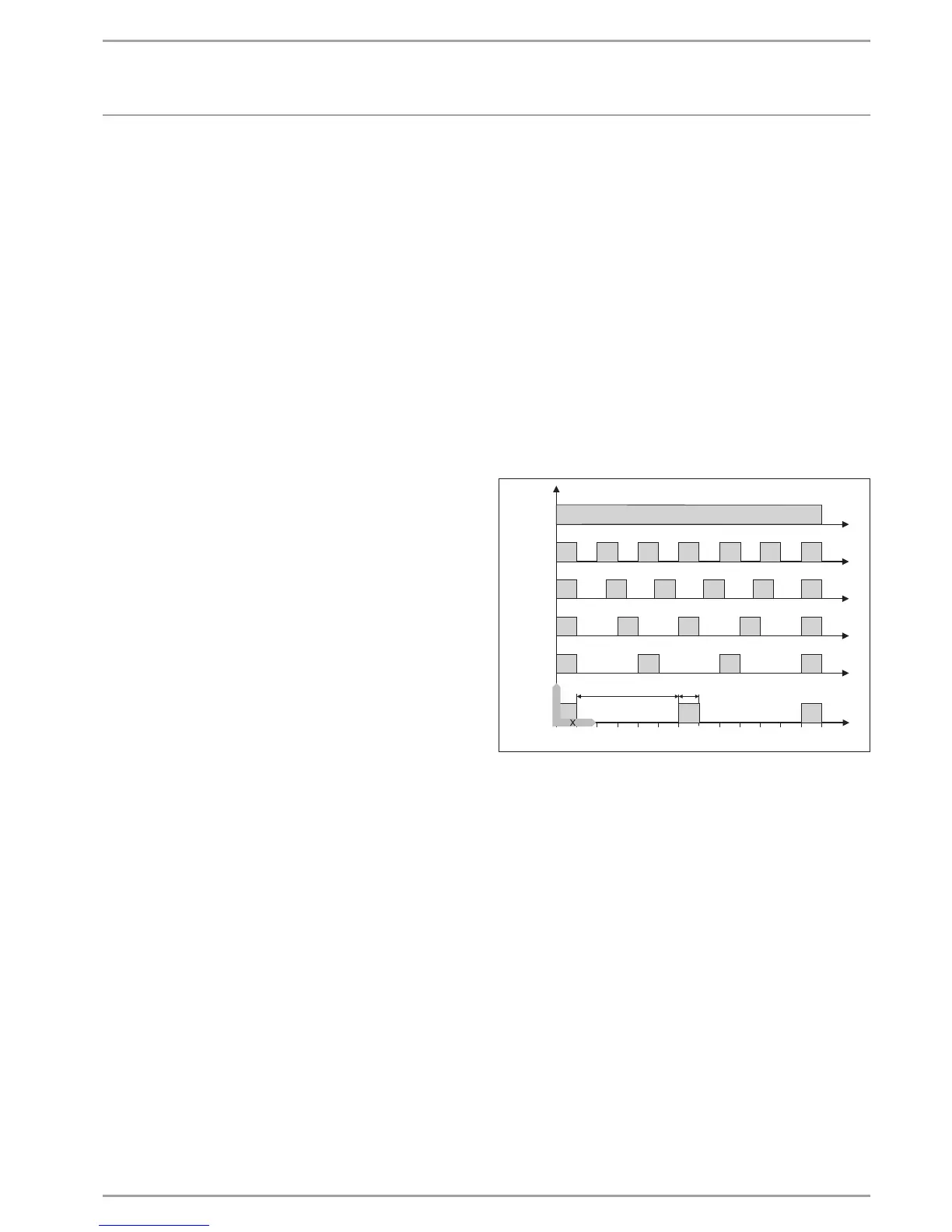
PUMP CYCLES
- Heating circuit pump control
The PUMP CYCLES parameter only applies to the direct heating
circuit1, i.e. for heating circuit pump 1.
This parameter can be switched ON or OFF. In the OFF position,
the heating circuit pump does not cycle. It will operate constantly.
It is only switched off in summer mode.
As soon as you set the parameter to ON, the heating circuit pump
is switched according to a fixed temperature curve for the outside
temperature.
The heating circuit pump start pulse is always 5minutes.
The heating circuit pump for heating circuit 1 always starts with
each heat pump start. The pump runs on for 5 minutes after the
heat pump has been shut down. This is where the start duration is
brought to bear, e.g. at an outside temperature of 5°C, the pump
starts 3 times per hour for 5minutes each time.
0 10 20 30 40 50 60
< -10
-10
-5
0
5
10
Y
2
1
84�03�01�0039
Y Outside temperature in °C
X Time in minutes
1 Pause
2 Pump runtime
- Pump kick
To prevent the pumps seizing up, for example over summer, the
pumps are switched on for 10 seconds after every 24 hour period
of inactivity. This applies to all pumps.
- Heating circuit pump control with FE7 / FEK remote control
connected
In conjunction with the FE7 or FEK remote control, after switching
condition
ϕ
ACTUAL room
>ϕ
SET room
+ 1K
the relevant heating circuit pump is switched off and the mixer
moves to CLOSE. This only applies if the room sensor influence is
set to K > 0. Reverse switching is subject to the following condition:
ϕ
ACTUAL room
>ϕ
SET room
The summer mode is also effective for the relevant heating circuit
when operating with an FE7 or FEK remote control.
 Loading...


