OPERATION
Menu structure
20 | WPM 3 www.stiebel-eltron.com
HEATING CURVE VIEW
Adjustment of programmed operation – changeover between
comfort and ECO mode
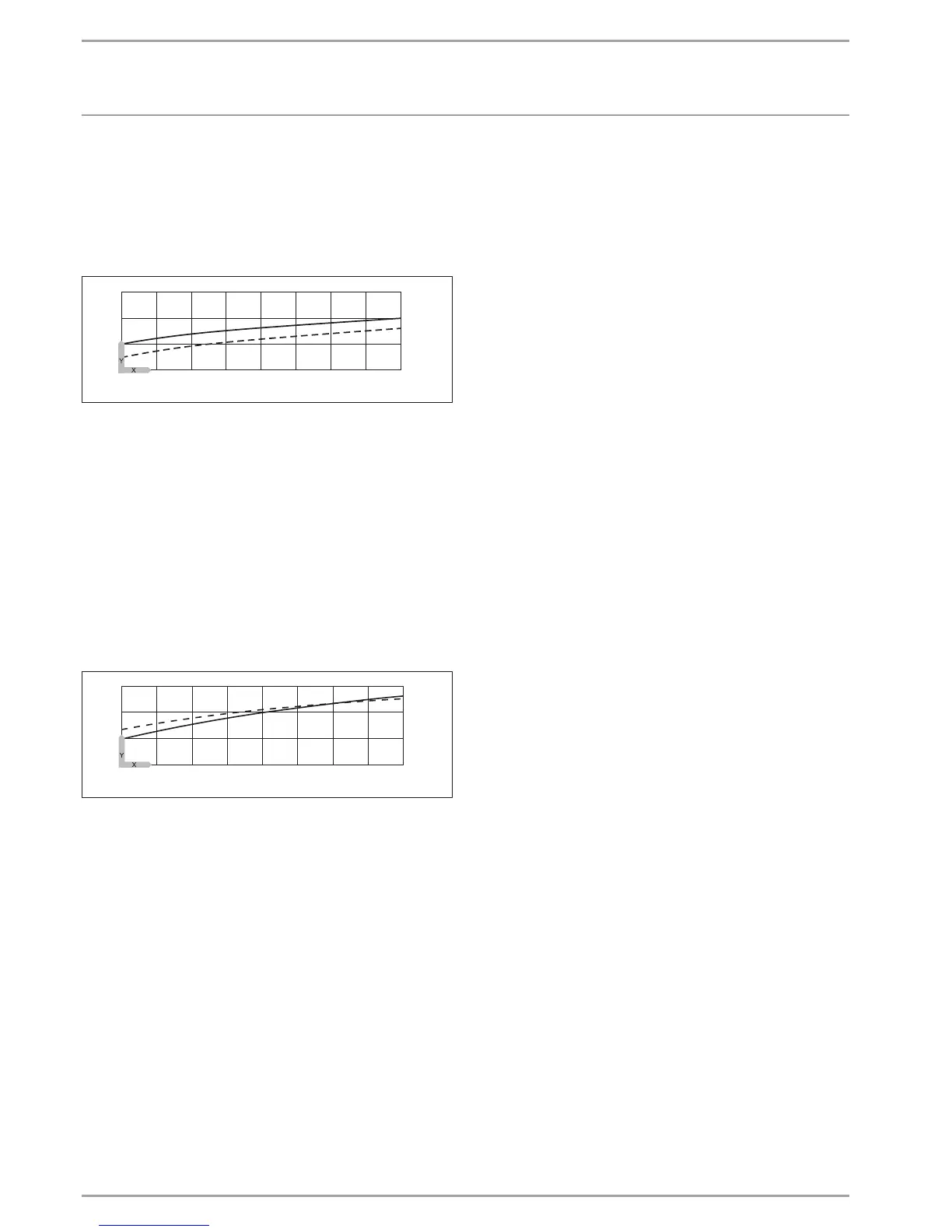
The diagram shows the graph with the set heating curve relating
to a set room temperature for comfort mode. The second, dotted
line relates to a set room temperature for ECO mode.
60
40
20
0
1
2
20 15 10 5 0 -5 -10 -15 -20
26�03�01�1915
Y Return / flow temperature [°C]
X Outside temperature [°C]
1 Comfort mode
2 ECO mode
Example of adapting a heating curve:
With heating systems, the temperature in a building during the
transitional periods (spring and autumn) is too low when outside
temperatures are between 5 °C and 15°C, despite open radiator
valves, but is OK at outside temperatures ≤ 0°C. This problem can
be remedied with a parallel shift and a simultaneous reduction
of the heating curve.
Heating curve 1.0 was initially adjusted relative to a set room tem-
perature of 20 °C. The dotted line indicates the modified heating
curve at 0.83 and a modified set room temperature of 23.2 °C.
60
40
20
0
20 15 10 5 0 -5 -10 -15 -20
26�03�01�1916+
Y Return / flow temperature [°C]
X Outside temperature [°C]
STANDARD SETTING
BUFFER OPERATION
When using a buffer cylinder, set this parameter to ON.
The buffer charging pump always operates in conjunction with
the compressor.
The “buffer operation OFF” setting is intended for installations
without a buffer cylinder. In this case, this pump operates as a
heating circuit pump and runs constantly.
SUMMER MODE
Parameter SUMMER MODE enables you to define the point at
which the heating system is to switch to summer mode. Summer
mode can be switched on or off. There are 2 adjustable parameters
for this function.
OUTSIDE TEMPERATURE
Adjustable outside temperature
BUILDING HEAT BUFFER
This parameter lets you choose whether an average outside tem-
perature should be determined, according to the type of building.
You can choose from 4 settings.
Setting "0": The outside temperature is not adjusted. The average
and the building-specific outside temperatures are identical to
the current outside temperature; direct comparison between the
selected and current outside temperature.
Setting "1": Slight adjustment of the outside temperatures (aver-
aged over a 24h period), e.g. for timber construction with rapid
heat transfer.
Setting "2": Moderate adjustment of the outside temperature (av-
eraged over a 48h period), e.g. brick construction with thermal
insulation and average heat transfer.
Setting "3": Major adjustment of the outside temperature (aver-
aged over a 72h period). House with slow heat transfer.
If the determined outside temperature is ≥ the selected outside
temperature, both heating circuits (if installed) enter summer
mode; reverse hysteresis –1 K.
With fixed value control, summer mode is disabled for heating
circuit 1.
FLOW PROP HEATING CIRC
Flow proportion for temperature capture of heating circuit 1, heat-
ing circuit control unit
Setting range 0 to 100 %:
Here you can select flow or return temperature control
for the heating system.
Setting 0: Heating system with return temperature control
Setting 100: Heating system with flow temperature control
Setting 80: Spread control (20 % return and 80 % flow control)
Setting 50: Spread control (50 % return and 50 % flow control)
Setting 30: Spread control (70 % return and 30 % flow control)
Generally, values below 80 (recommendation: 50) should normally
be set for heating circuit 1 to limit the influence of the flow temper-
ature. Particularly in spring and autumn, the flow temperature is
naturally subject to strong fluctuations because of the heat pump
being switched on and off.
MAXIMUM RETURN TEMP
If the temperature at the return sensor reaches this set value
during heating mode, the heat pump is immediately switched
off. This safety function prevents the high pressure limiter from
responding. No fault message is issued when this value is reached.
In DHW mode the return temperature is not scanned.
 Loading...


