OPERATION
Menu structure
www.stiebel-eltron.com WPM 3| 19
ROOM INFLUENCE
Adjustable from 0 to 20 and OFF (standard setting: 05)
With the FE7 remote control connected, the room temperature
sensor only serves to record and display the actual room temper-
ature; it has no influence on the actual control. The remote control
can be used to adjust the room temperature for heating circuit 1
or 2 by ± 5 °C in automatic mode only. This set value adjustment
applies to the current heating time, not to the setback time.
At the same time, the setting “0 to 20” serves to control the room
temperature-dependent night setback. This means that the heat-
ing circuit pump switches off at the changeover from the heating
phase to the setback phase. It remains off until the actual room
temperature falls below the set room temperature. After this, the
system continues to regulate in weather-compensated mode.
If the room temperature is to be included in the control loop, the
room sensor influence must be set to a value > 0. The room sensor
influence has the same effect as the outside temperature sensor
has on the return temperature, except that the effect is 1 to 20
times greater, depending on the factor set.
- Room temperature-dependent return / flow temperature
with weather compensation
With this type of control, a controller cascade is formed from both
weather-compensated and room temperature dependent return/
flow temperature control. This means that the weather-compen-
sated return/flow temperature control sets a default return/flow
temperature that is corrected by the overriding room temperature
control in accordance with the following formula:
∆ϕ
R
= (ϕ
Rset
− ϕ
Ractual
) * S * K
Because a substantial proportion of the control is already handled
by the weather-compensated control, the room sensor influence K
can be set lower than with pure room temperature control (K=20).
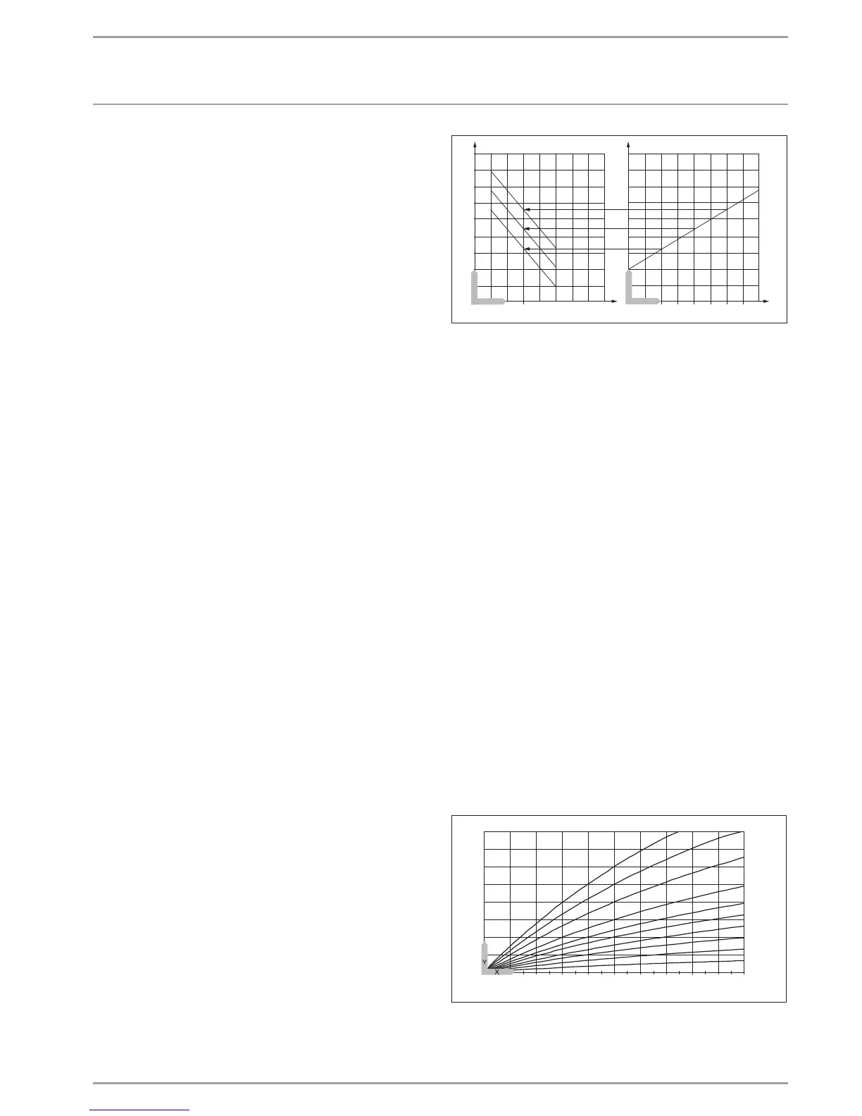
The graph shows the control method with the set factor K=10 (room
influence) and a heating curve S=1.2
- Room temperature control with weather-compensation.
This type of control offers two main benefits:
Incorrectly set heating curves are corrected by the room sensor
influence K; the smaller factor K means the control unit works in
a more stable manner.
However, observe the following for all control units with room
sensor influence:
- The room temperature sensor must capture the room tem-
perature accurately.
- Open doors and windows greatly affect the control result.
- All radiator valves in the lead room must be fully open at all
times.
- The temperature inside the lead room affects the entire heat-
ing circuit.
If the room temperature is to be included in the control loop, the
room sensor influence must be set to a value > 0.
20
30
40
20
50
60
70
80
90
1917 18 21 22 23 24 25
0
10
0
20
-20
15
10
5
-5
-10
-15
Y
X 1
Y
X 2
1
1
1
2
3
4
5
26�03�01�1917
Y Flow temperature [°C]
X 1 Room temperature [°C]
X 2 Outside temperature [°C]
1 Room sensor influence at K = 10 and S = 1.2 and control
deviation +/- 2 K
2 Heating curve S = 1.2
3 Weather-compensated set flow temperature at ϕ
A
=
- 10°C
4 Weather-compensated set flow temperature at ϕ
A
= 0 °C
5 Weather-compensated set flow temperature at ϕ
A
= +
10°C
HEATING CURVE RISE
Menu item HEATING CURVE RISE enables you to set one heating
curve each for heating circuits1 and 2.
Note: Your contractor will have set a building and system-specific
optimum heating curve for every heating circuit. For heating cir-
cuit 1 the curve relates to the heat pump return temperature, for
heating circuit 2 to the mixer flow temperature.
When you adjust the heating curve on the heat pump manager,
the calculated set return or flow temperature is shown at the top
of the display, subject to the outside temperature and the set
room temperature.
As soon as you have preselected a temperature in menu SETTINGS
/ HEATING / STANDARD SETTING under parameter FIXED VALUE
OPERATION, heating curve 1 is hidden from view and the display
shows SETFIXED TEMPERATURE with the relevant temperature.
At the factory, heating curve 0.6 is set for heating circuit1 and
heating curve 0.2 for heating circuit2. These heating curves relate
to a set room temperature of 20 °C.
1,5
2
1,2
1
0,6
0,4
0,2
2,53
20
18
16
14
12
10
8
6
4
2
0
-2
-4
-6
-8
-10
-12
-14
-16
-18
-20
100
80
60
40
20
0,8
26�03�01�1300
Y Heating circuit 1, heat pump return temperature [°C]
Heating circuit 2, heat pump flow temperature [°C]
X Outside temperature [°C]
 Loading...


