23MS 201, MS 201 C, MS 201 T, MS 201 TC
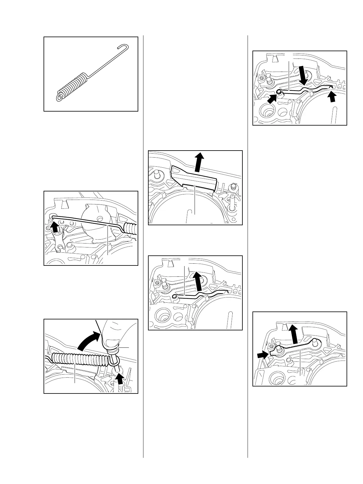
: The turns of the brake spring
must be tightly against one
another in the relaxed condition.
If this is not the case, replace the
brake spring.
If the groove in the spring's anchor
pin is worn, install a new pin, b 5.5
– The stop must be installed.
: Attach the brake spring (1) to the
brake lever (arrow).
: Use the assembly tool (2)
1117 890 0900 to attach the
brake spring (1) to the anchor pin
(arrow).
161RA040 TG
7013RA024 TG
1
7013RA025 TG
2
1
– Lubricate the brake lever with
STIHL lubricant, b 14
– Reassemble all other parts in the
reverse sequence.
5.4 Flat Spring
The flat spring and hand guard cam
hold the hand guard in position.
– Remove the brake lever, b 5.3
: Remove the stop (1).
: Pull out the flat spring (1), check
it and replace if necessary.
7013RA027 TG
1
Installing
: Push the flat spring (1) into the
guides (arrows).
– Lubricate the flat spring with
STIHL lubricant, b 14
– Install the stop.
– Reassemble all other parts in the
reverse sequence.
5.5 Pins
The pins secure the springs. Worn
pins must be replaced – the brake
spring may pop out during this
operation.
For greater clarity, all parts have
been removed from the pins in the
following illustrations.
: Apply suitable tool to tab (arrow)
to pry the link (1) out of its seat.
Check and replace if necessary.
7013RA028 TG
1
7013RA029 TG
1