72 MS 201, MS 201 C, MS 201 T, MS 201 TC
Installing
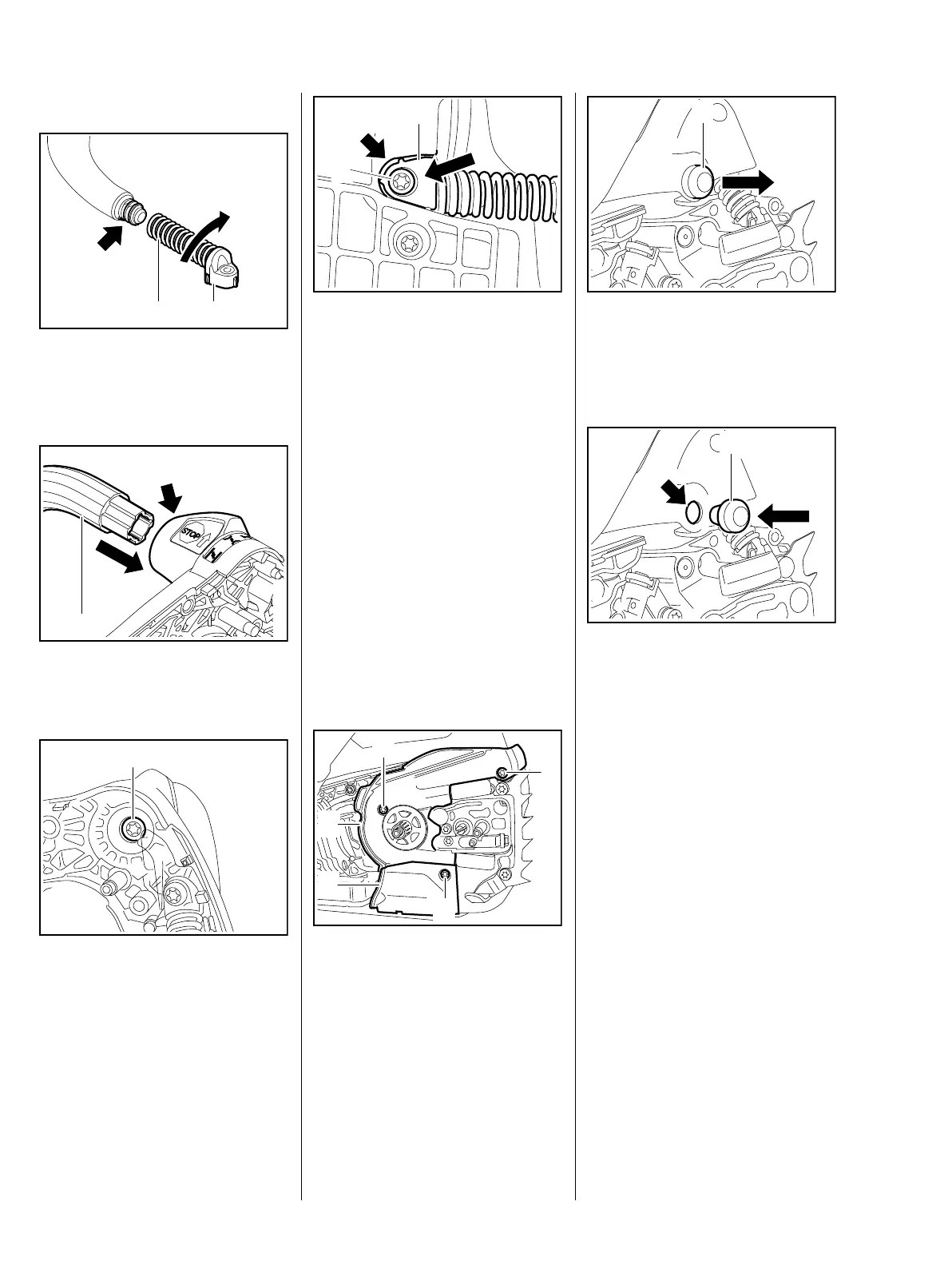
: Screw the AV spring (2) with
bearing plug (1) onto the
handlebar (arrow) as far as stop.
: Push the handlebar (1) into its
seat (arrow).
: Insert and tighten down the
screw (1) firmly.
7013RA086 TG
1 2
7013RA087 TG
1
7013RA088 TG
1
: Push the bearing plug (1) into its
seat (arrow) on the underside of
the machine.
: Coat the screw (2) with Loctite, fit
it and tighten it down firmly, b 14
– Install the switch shaft and
handle molding, b 10.3
9.4 Stop Buffer on Handle
Housing (MS 201)
– Disengage the chain brake and
remove the chain sprocket cover,
bar and chain.
– Remove the clutch drum, b 4.2
: Take out the screws (1).
: Remove covers (2) and (3).
1
7013RA083 TG
2
7013RA191 TG
1
1
1
2
3
: Pry out and replace the stop
buffer (1).
Installing
– Coat taper of stop buffer with
STIHL press fluid, b 14
: Position the stop buffer (1) so
that its taper points in the
direction of the handle housing.
: Press the stop buffer (1) in the
hole (arrow) and make sure it is
properly seated.
– Reassemble all other parts in the
reverse sequence.
7013RA089 TG
1
7013RA090 TG
1