74 MS 201, MS 201 C, MS 201 T, MS 201 TC
10. Control Levers
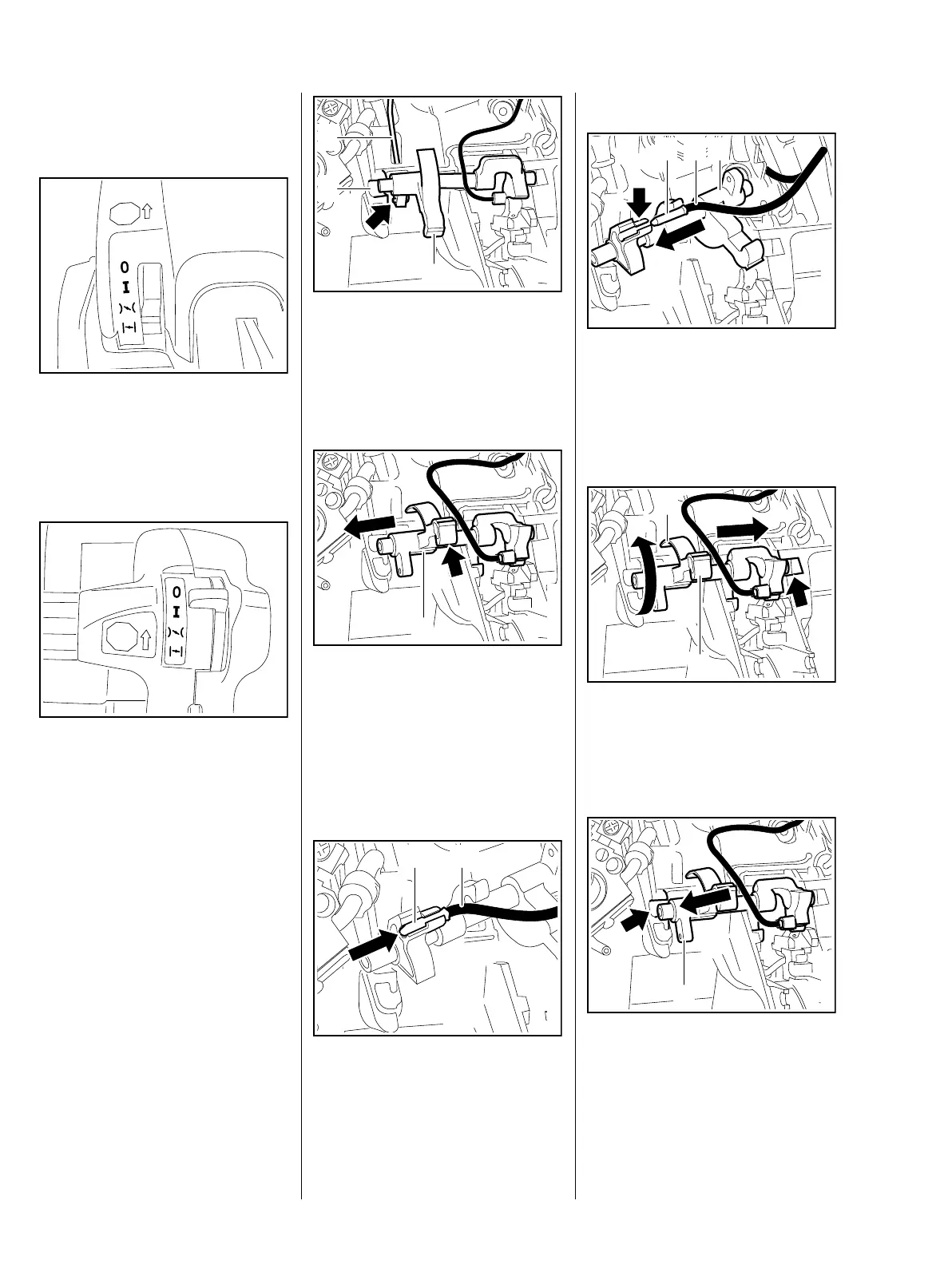
10.1 Master Control Lever
MS 201
The positions of the Master Control
lever are described in the instruction
manual.
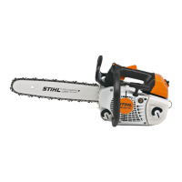
MS 201 T
The positions of the Master Control
lever are described in the instruction
manual.
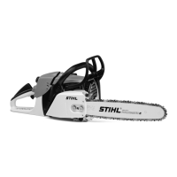
10.1.1 Switch Shaft (MS 201)
– Remove the air filter, b 12.1
– Remove the handle molding,
b 10.2
– Remove the choke and throttle
rods, b 10.3.1
– Remove the lockout lever and
throttle trigger, b 10.2
STOP
7013RA200 TG
STOP
7013RA201 TG
: Pry the switch shaft (1) out of its
mount (2).
: Pull the choke rod (3) out of the
hole (arrow).
: Lift the switch shaft (1) a little and
rotate it towards the intake
manifold until the lever (arrow) is
above the handle housing.
: Pull out the switch shaft (1) in
direction of ignition side.
: Disconnect terminal (1) of short
circuit wire (2).
– Inspect the switch shaft and
replace if necessary.
3
7013RA202 TG
1
2
7013RA203 TG
1
7013RA204 TG
1 2
Installing
: Fit the short circuit wire (1) over
the switch shaft (2).
: Push the connector sleeve (3)
into its seat (arrow) as far as stop.
: Push the switch shaft (1) into the
pivot mount (arrow) and rotate it
so that the lever (2) is above the
handle housing.
: Lift the switch shaft (1) a little and
push it into the pivot mount
(arrow) until it snaps into position.
7013RA205 TG
1 23
7013RA206 TG
2
1
7013RA207 TG
1