77MS 201, MS 201 C, MS 201 T, MS 201 TC
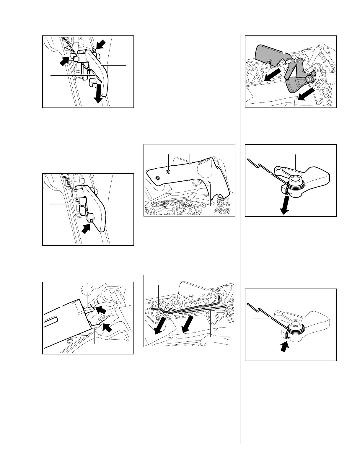
: Push leg (1) of torsion spring in
direction of rear handle.
: Press the lockout lever (2) into
the mounts until it snaps into
place.
: Attach the torsion spring (1) to
the lockout lever (arrow).
: Push the lugs (1) of the handle
molding (2) under the projections
(arrows).
– Push down the handle molding
until it snaps into position.
7013RA221 TG
2
1
7013RA222 TG
1
2
7013RA223 TG
1 2
– Check operation
– Throttle trigger must be
blocked when the lockout lever is
not operated and the switch lever
must be blocked in the direction
of cold start when the throttle
trigger is not operated.
– Reassemble all other parts in the
reverse sequence.
10.3 Throttle Trigger /
Lockout Lever (MS 201 T)
: Take out the screws (1).
: Carefully remove the handle
molding (2) – rods and levers
may fall out.
: Pull out the throttle rod (1) and
choke rod (2), b 10.3.2
7013RA224 TG
2
1
1
1
1
7013RA225 TG
2
: Remove the lockout lever (1) and
throttle trigger (2).
: Disconnect the torsion spring (1)
from the throttle trigger (2).
– Check individual parts, replace if
necessary
Installing
: Fit and connect torsion spring (1)
– note installed position (arrow).
7013RA226 TG
2
1
7013RA227 TG
1
2
7013RA228 TG
1