29MS 271 C, MS 291 C
: Attach the brake cable (1) to the
bore (arrow) in the brake
lever (2).
: Position the brake cable (1) in the
guide (arrow).
– Install the switch lever, b
10.3.1
– Install the throttle trigger, b 10.3
– Reassemble all other parts in the
reverse sequence.
– Check operation and adjust the
brake cable, b
5.4.1
2710RA079 TG
1 2
5902RA262 TG
1
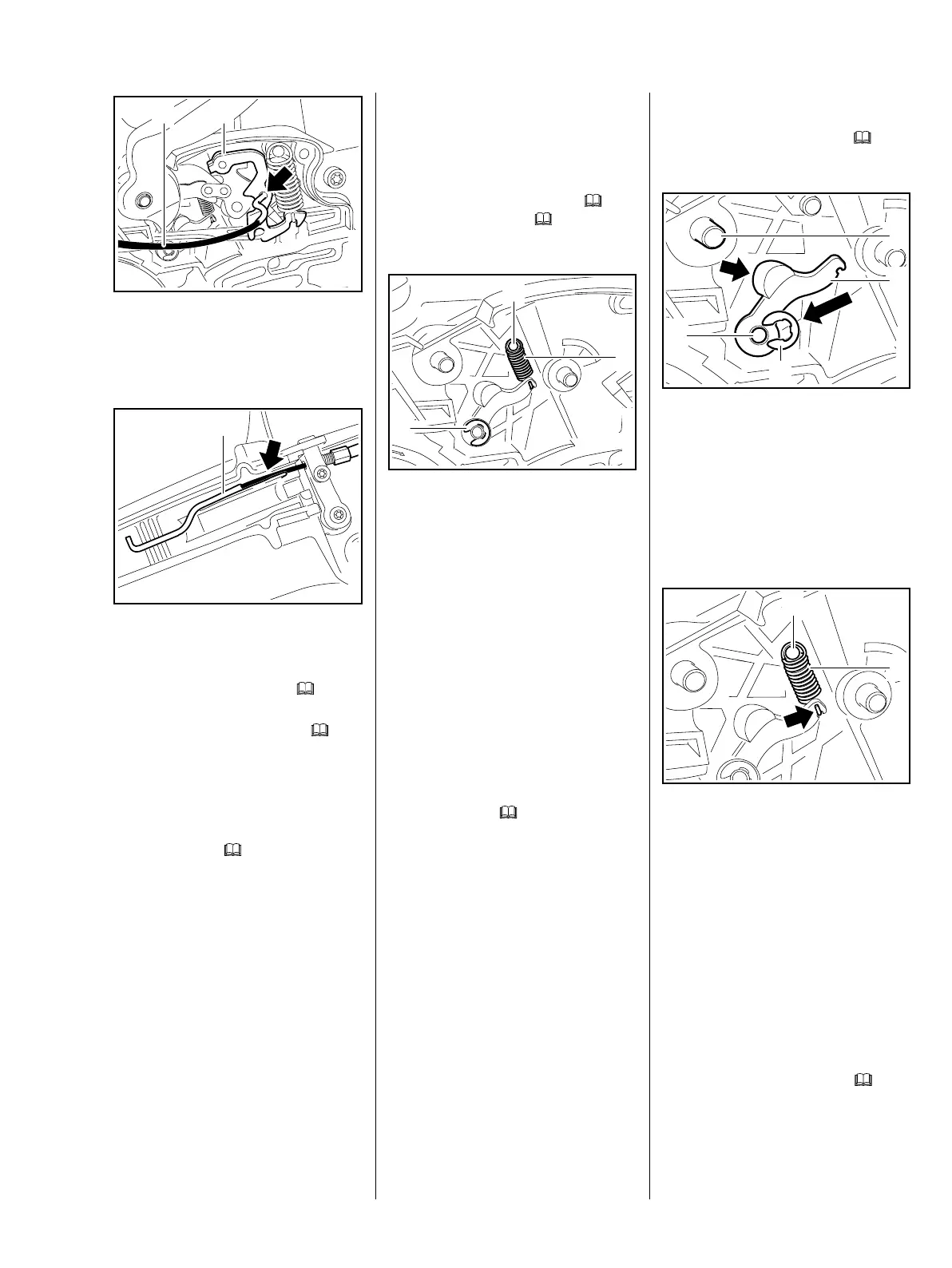
5.5 Cam Lever
The cam lever defines the locked
position of the hand guard.
– Remove the brake lever, b
5.3,
QuickStop Super, b
5.4
: Disconnect the spring (1) from
the anchor pin (2).
– Disconnect the spring (1) from
the cam lever and remove it.
: Remove the retaining ring (3).
– Pull off the cam lever.
– Check the cam lever, spring and
condition of cam guide n the
hand guard and replace if
necessary.
– Inspect all pivot pins and replace
if necessary, b 5.6
2710RA051 TG
1
2
3
Installing
– Lubricate the pivot pins, b
14
: Position the cam lever (1) so that
its cam (arrow) faces the pin (3).
: Push the cam lever (1) on to the
pivot pin (2).
: Fit the retaining ring (4).
: Attach the spring (1) to the cam
lever so that the open side of the
spring hook (arrow) is visible.
: Attach the spring (1) to the
anchor pin (2).
The cam lever is not yet under
tension – the spring may become
detached.
– Reassemble all other parts in the
reverse sequence.
– Lubricate the cam lever, b 14
2710RA053 TG
1
3
2
4
2710RA054 TG
2
1