74 MS 271 C, MS 291 C
Installing
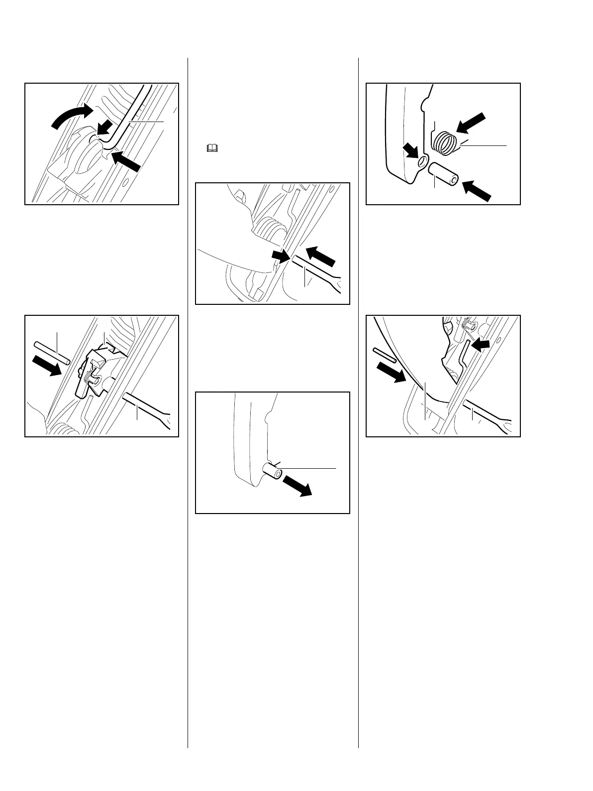
: Connect the brake cable (1) to
the bore (arrow) in the switch
lever.
– Turn the switch lever so that it
faces up.
: Use a drift (2) to center the switch
lever (1).
: Drive home the pin (3) until it is
recessed by same amount at
both sides.
– Reassemble in the reverse
sequence.
– Check operation of switch lever
by operating the lockout lever.
5902RA332 TG
1
5902RA333 TG
1
2
3
10.3.2 Lockout Lever –
QuickStop Super
Lubricate sliding and bearing points
with grease after disassembly.
– Remove the handle molding,
b
10.3
: Use a drift (1) to drive out the
pin (arrow).
– Take out the lockout lever.
: Push out the bushing (1).
– Remove the torsion spring.
– Inspect the lockout lever, throttle
trigger and bushing, replace as
necessary.
5902RA334 TG
1
219RA453 TG
1
Installing
: Position the torsion spring (1)
and fit it in the lockout lever.
: Push the bushing (2) into the
bore (arrow) – the torsion spring
is held in position.
– The torsion spring (arrow) must
locate against the tank housing.
: Use a drift (2) to center the
lockout lever (1).
– Drive home the pin until it is
recessed by same amount at
both sides.
– Reassemble all other parts in the
reverse sequence.
– Check operation.
219RA455 TG
1
2
5902RA335 TG
2
1