52 MS 271 C, MS 291 C
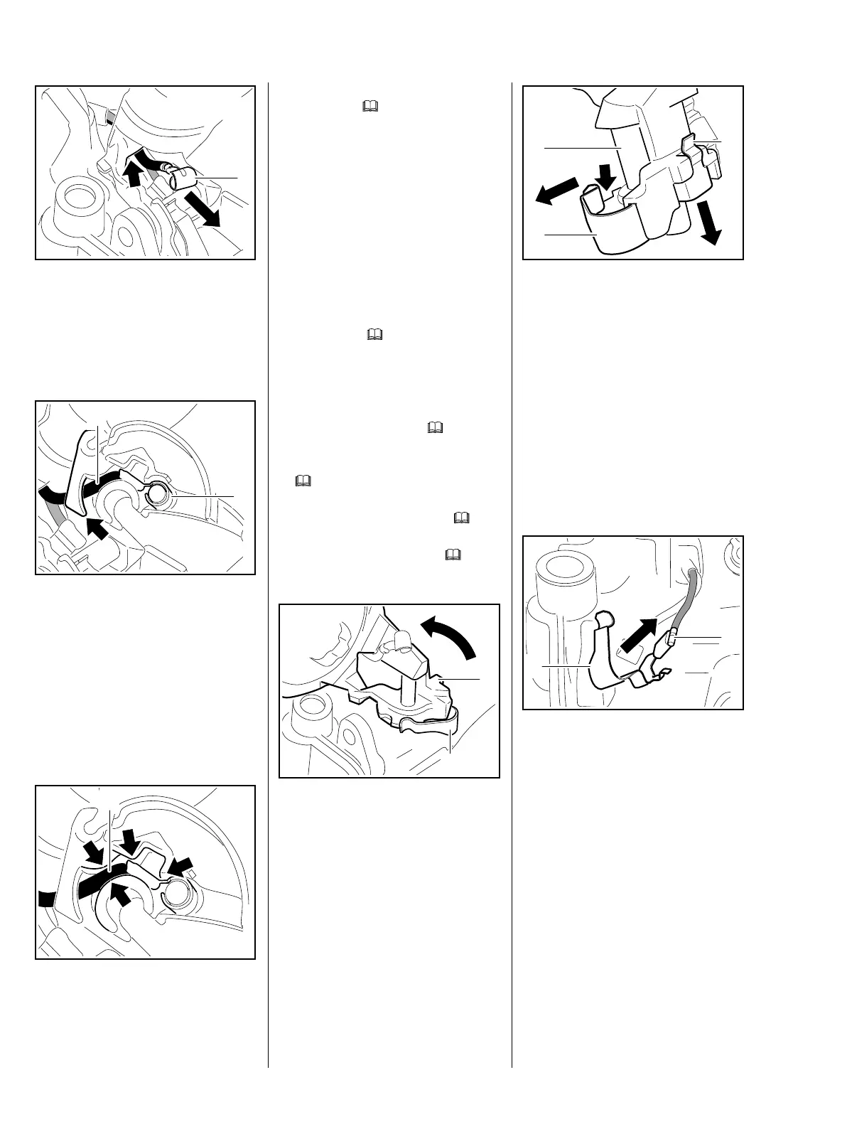
: Pass the ring terminal (1) through
the opening (arrow) in the filter
base.
– Place the switch shaft in position.
: Position the short circuit wire (1)
behind the tab (arrow).
: Position the ring terminal (2) so
that the gap in the ring faces
down.
: Push the ring terminal (2) onto
the peg as far as stop.
: Push the short circuit wire (1) into
the guides (arrows).
2710RA154 TG
1
2710RA329 TG
1
2
5902RA199 TG
1
– Install the switch shaft and check
operation, b
10.1
– Reassemble all other parts in the
reverse sequence.
7.7.3 Ground Wire
Test and install the ground wire as
described for the short circuit wire.
– Check for contact and continuity
and replace the wiring harness if
necessary, b
7.7
7.7.4 Contact Spring
– Remove the shroud, b
6.4
– Remove the choke rod,
b
10.3.3
– Remove the switch shaft, b 10.1
– Remove the filter base, b
12.3
: Carefully turn the filter base (1)
until the seat of the contact
spring (2) is visible.
2710RA156 TG
2
1
: Lift the contact spring (2) a little
and ease it over the
bead (arrow).
: Lift the tab (1) a little and slide the
contact spring (2) out of the filter
base (3).
– Pull the contact spring off the
ground wire, check and replace if
necessary.
Installing
: Push the contact spring (1) fully
onto the ground wire's flag
terminal (2).
2710RA162 TG
2
1
3
2710RA158 TG
2
1