35MS 271 C, MS 291 C
– Line up the flange and fit it over
the studs.
: Fit the test flange (1)
1119 850 4201.
: Fit the sleeves (2)
5910 893 1701.
: Fit the nuts (3) and tighten them
down firmly.
6.2.2 Vacuum Test
Oil seals tend to fail when subjected
to a vacuum, i.e. the sealing lip lifts
away from the crankshaft during the
piston's induction stroke because
there is no internal counterpressure.
A test can be carried out with pump
0000 850 1300 to detect this kind of
fault.
: Connect hose (1) of pump
0000 850 1300 to the
nipple (arrow).
2710RA080 TG
1
3
2
2
3
2710RA081 TG
2
34
1
: Push ring (2) to the left
– vacuum test.
: Operate the lever (3) until the
pressure gauge (4) indicates a
vacuum of 0.5 bar.
If the vacuum reading remains
constant, or rises to no more than
0.3 bar within 20 seconds, it can be
assumed that the oil seals are in
good condition.
If the pressure continues to rise
(reduced vacuum in the engine), the
oil seals must be replaced, b
6.3.
– After finishing the test, push the
ring to the right to vent the pump.
– Continue with pressure test,
b
6.2.3
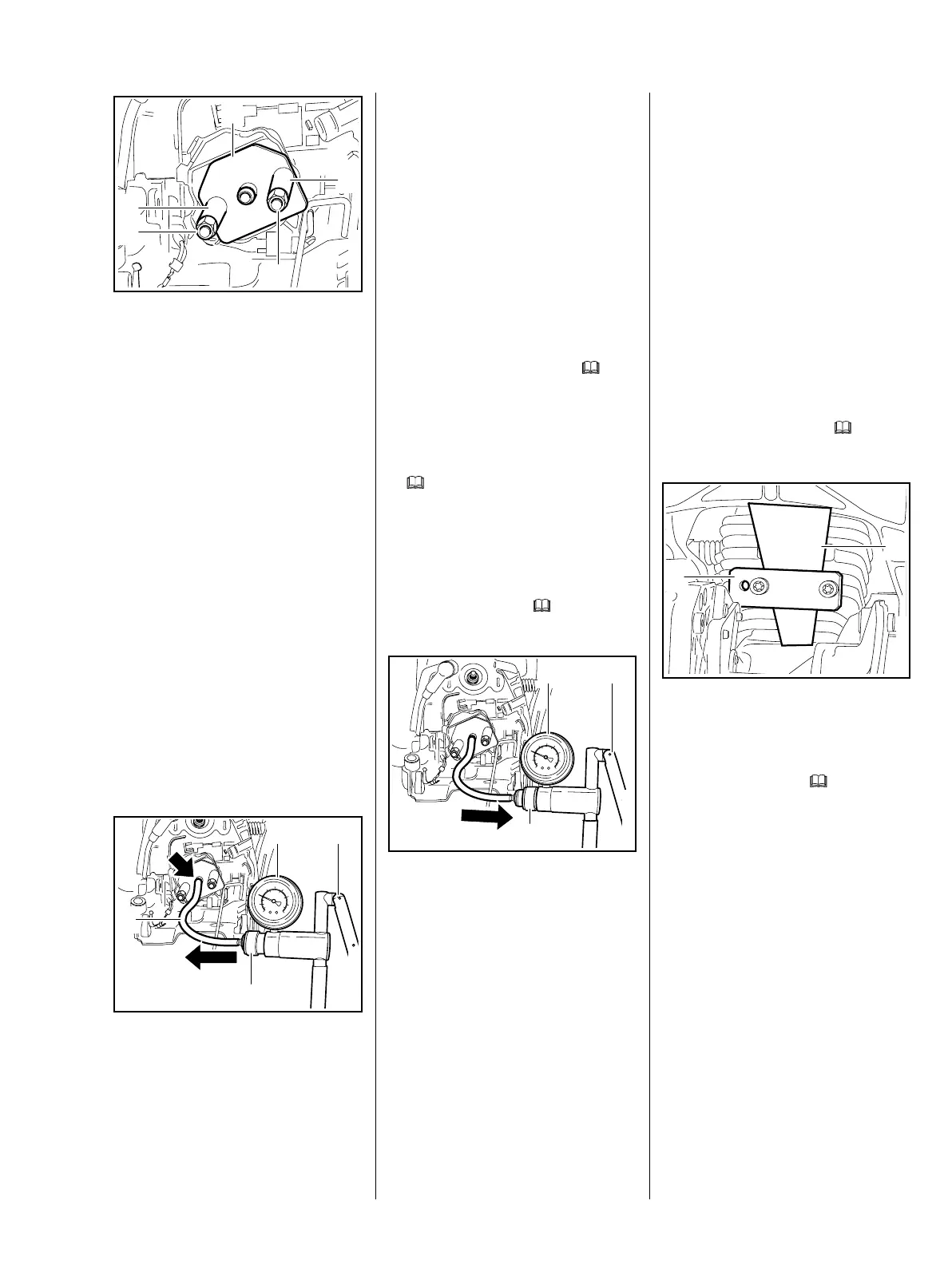
6.2.3 Pressure Test
Carry out the same preparations as
for the vacuum test, b 6.2.2
: Push ring (1) to the right
– pressure test.
: Operate the lever (2) until the
pressure gauge (3) indicates a
pressure of 0.5 bar. If this
pressure remains constant for at
least 20 seconds, the engine is
airtight.
2710RA082 TG
1
23
– If the pressure drops, the leak
must be located and the faulty
part replaced.
To find the leak, coat the suspect
area with soapy water and
pressurize the engine again.
Bubbles will appear if a leak exists.
– After finishing the test, push the
ring to the left to vent the pump –
disconnect the hose.
– Remove the flange
1119 850 4201 from the intake
manifold.
– Install the carburetor, b
12.5
: Remove the flange (1)
5910 855 4201 and sealing
plate (2) 0000 855 8106.
– Install the muffler, b
6.1
– Use a blunt tool to push home the
new plugs
– take care not to damage the
plugs.
– Reassemble all other parts in the
reverse sequence.
2710RA083 TG
2
1