24 MS 271 C, MS 291 C
: Use the assembly tool (2)
1117 890 0900 to attach the
brake spring (1) to the anchor
pin (arrow).
– Lubricate the brake lever, cam
lever and slot in hand guard,
b
14
– Reassemble all other parts in the
reverse sequence.
5.4 Brake lever on machines
with QuickStop Super
– Troubleshooting, b 3.2
– Remove the brake band, b 5.2
– Engage the chain brake.
The brake spring is now relaxed.
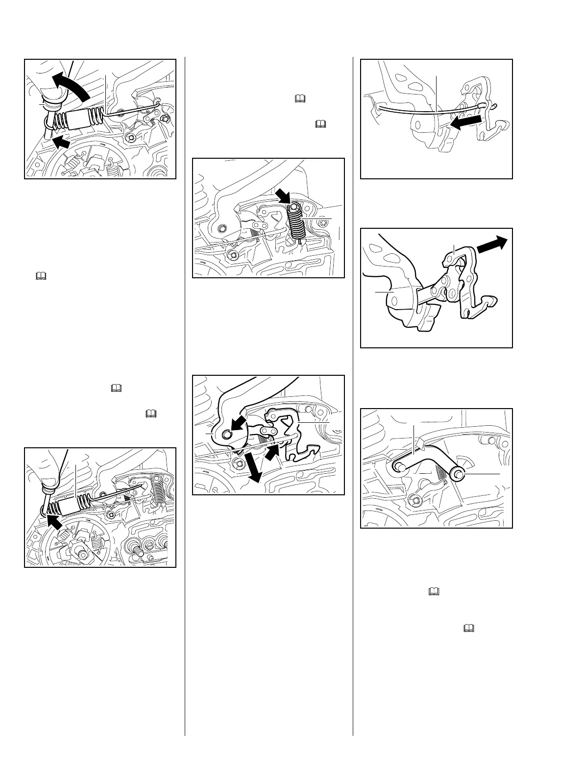
: Use the assembly tool
1117 890 0900 to disconnect the
brake spring (1) from the anchor
pin (arrow).
off
2710RA030 TG
1
2
off
off
2710RA031 TG
1
– Remove the brake spring from
the brake lever.
– Remove the shroud, b
6.4
– Remove the fan housing, b
8.2
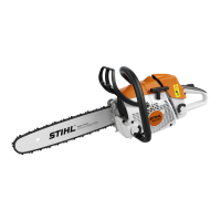
: Disconnect the spring (1) from
the anchor pin (arrow).
– Remove the brake spring (1)
from the brake lever.
: Pull the hand guard (1) and brake
lever (2) off the pivot
pins (arrows) together.
– Remove the hand guard and
brake lever.
off
2710RA032 TG
1
off
2710RA033 TG
2
1
: Disconnect the brake cable (1).
: Take the brake lever (2) out of the
hand guard (1).
: Remove the spacer washer (1)
and strap (2).
– Inspect all pivot pins and replace
if necessary, b
5.6
– Inspect the cam lever and
replace if necessary, b
5.5
5902RA046 TG
1
5902RA047 TG
1
2
off
2710RA034 TG
1
2