70 MS 271 C, MS 291 C
10. Control Levers
10.1 Master Control Lever
The positions of the Master Control
lever are described in the instruction
manual.
10.1.1 Removing and Installing
– Remove the air filter, b 12.1
– Remove the choke rod,
b 10.3.3
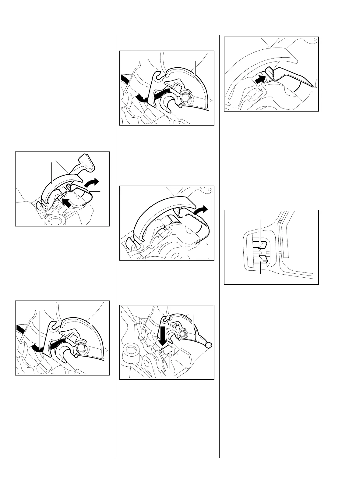
– Set the switch lever (1) to "
0".
: Pry out the switch lever (1) at the
opening (arrow) and remove it,
lifting the contact spring (2)
slightly at the same time
– no more than 2 mm.
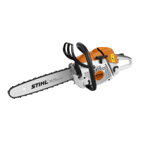
– Remove the short circuit wire (1)
from the switch lever, b 7.7.2
: Remove the switch lever (2),
check it and replace if necessary.
2710RA192 TG
1
2
5902RA584 TG
1 2
Installing
– Place the switch lever (2) in
position.
– Fit the short circuit wire (1) on the
switch lever, b 7.7.2
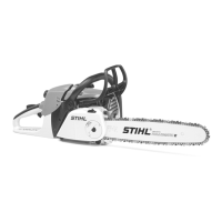
: When installing the switch lever,
lift the contact spring (1) a little
– no more than 2 mm.
: Push the switch lever (1) onto the
filter base's pivot pin (2) until it
snaps into position.
5902RA584 TG
1 2
2710RA155 TG
1
2710RA193 TG
1
2
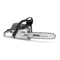
: Check operation.
– Short circuit wire's ring terminal
must touch the contact
spring (arrow) in position "
0".
– Reassemble all other parts in the
reverse sequence.
10.2 Throttle Trigger/Lockout
Lever
: To remove the handle molding,
press the tabs (1) on the
underside apart and push them
through the rear handle.
5902RA264 TG5902RA307 TG
1
1