0478 111 9940 A - EN
46
7.1 General
● Place the machine on level and firm
ground when performing all the
operations described.
7.2 Assembling the handlebar
Fitting the handlebar sleeves:
● Fit protective sleeves (I) onto
handlebar (1). Position the square hole
on the inner side of the handlebar, the
bores in the handlebar and the square
hole in the handlebar sleeve must be
aligned.
Assembling the handlebar:
● Fit handlebar (1) onto both lower
handlebar sections (2).
● Insert flat head bolts (G) through bores
from the inside to the outside and
tighten with rotary handles (H).
1 Attaching left anti-kink cable
protection:
● Insert all cables into anti-kink cable
protection (F).
● First insert the anti-kink cable protection
in upper bore (3) of the lower
handlebar.
● Then allow the anti-kink cable
protection to engage in lower slot (4) of
the lower handlebar.
2 Attaching right anti-kink cable
protection:
● The right anti-kink cable protection (F)
is attached in the same way as on the
left side.
7.3 Installing the cable guide
● Insert cable guide (E) into the
recesses in housing (1) and turn
towards the upper handlebar.
● Insert all cables into the cable guide.
● Allow the cable guide to engage in the
two bores provided using slight
pressure.
RM 545 VE:
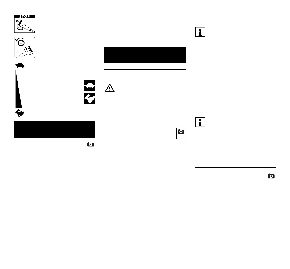
Stopping the engine
RM 545 T, RM 545 V,
RM 545 VE, RM 545 VM,
RM 545 VR:
Switching on self-propulsion
RM 545 V, RM 545 VE,
RM 545 VM, RM 545 VR:
Setting the driving speed
Slow – push Vario
drive lever forwards
Fast – pull Vario
drive lever rearwards
6. Standard equipment
Item Designation Qty.
A Basic unit 1
B Lower part of grass catcher
box
1
C Upper part of grass catcher
box
1
D Pin 2
E Cable guide
(RM 545, RM 545 T
2
1)
F Anti-kink cable protection
(RM 545, RM 545 T
2
1)
G Flat head bolt 2
H Rotary handle 2
I Handlebar sleeve 2
J Battery (RM 545 VE) 1
2
K Charger (RM 545 VE) 1
– Instruction manual 1
–Engine
instruction manual
1
7. Preparing the machine for
operation
Risk of injury!
Observe the safety instructions in
the section "For your safety" (Ö 4.).
Item Designation Qty.
3
Attach anti-kink cable protection (F)
only as shown. Cables must be
routed under the handlebar. Loosen
rotary handle (H) prior to assembly
if necessary.
RM 545, RM 545 T:
There are no cables on the right-
hand side of the handlebar,
therefore there is no anti-kink cable
protection on the right.
4

 Loading...